manualshive.com logo in svg
background image

Designer’s


Handbook

7

6.

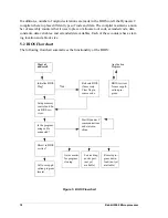
 The program enters a loop where it receives a fixed number of bytes which comprise a 
secondary

 loader program (pilot.bin sent by the PC) and writes those bytes to memory 

location

 0x4100. After all of the bytes are received, program execution jumps to 

0x4100.

7.

 The secondary loader does a wrap-around test to determine how much RAM is avail-
able,

 and reads the flash ID. This information is made available for transmittal to 

Dynamic

 C when requested.

8.

 The secondary loader now enters a finite state machine (FSM) that is used to imple-
ment

 the Dynamic C/Target communications protocol. Dynamic C compiles the core of 

the

 regular BIOS and sends it to the target at address 0x00000 which is still mapped to 

RAM.

 Note that this requires that the BIOS core be 0x4000 or less in size. 

9. The

 FSM checks the memory location 0x4001 (previously set to zero) after receiving 

each

 byte. When the compilation and loading to RAM of the BIOS is complete, 

Dynamic

 C signals the target that it is time to run the BIOS by sending a one to 0x4001. 

10.

 The BIOS runs some initialization code including setting up the serial port for 115200 

baud,

 setting up serial interrupts and starting a new FSM. 

11.The

 BIOS code modifies a jump instrucction near the beginning of the program so that 

the

 next time it runs, it will skip  Step 12.

12.The

 BIOS copies itself to flash at 0x80000, and switches the mapping of flash and 

RAM

 so that RAM is at 0x80000 and flash is at 0x00000. As soon as this remapping is 

done,

 the BIOSís execution of instructions begins happening in flash. 

13.Dynamic

 C is now ready to compile a user program. When the user compiles his pro-

gram

 to the target, it is first written to a file, then the file is loaded to the target using the 

BIOS’

 FSM. The file is used as an intermediate step because fix-ups are done after the 

compilation

 is complete and all unknown addresses are resolved. The fix ups would 

cause

 extra wear on the flash if done straight to the flash. 

14.When

 the program is fully loaded, Dynamic C sets a breakpoint at the beginning of 

main

 and runs the program up  to the breakpoint. The board has been programmed, and-

Dynamic

 C is now is debug mode.

15.If

 the programming cable is removed and the target board is reset, the user’s program 

will

 start running automatically because the the BIOS will check the SMODE pins to 

determine

 whether to run the user application or enter the debug kernel. 

Содержание 2000

Страница 1: ...Rabbit 2000 Microprocessor Designers Handbook Revision C...

Страница 2: ...between the customer and Rabbit Semiconductor prior to use Life support devices or systems are devices or systems intended for surgical impantation into the body or to sustain life and whose failure...

Страница 3: ...17 5 2 BIOS Flowchart 18 5 3 Internally defined macros 19 5 4 Modifying the BIOS 19 5 5 Origin Directives to the Compiler 20 6 The System ID Block 23 6 1 Definition 23 6 2 Access 24 6 3 Reading the ID...

Страница 4: ...Rabbit 2000 Microprocessor...

Страница 5: ...mming cable connects a PC serial port to the pro gramming connector of the target microprocessor system Figure 1 Dynamic C Programming The Rabbit programming cable is a smart cable with an active circ...

Страница 6: ...2 Rabbit 2000 Microprocesssor...

Страница 7: ...ximum computation per watt is obtained in the range of 3 0 V to 3 6 V The highest clock speeds require 5 V The maximum clock speed with a 3 3 V sup ply is 18 9 MHz but it will usually be convenient to...

Страница 8: ...nt can be reduced by executing long strings of multiply zero by zero instructions Keep in mind that a Rabbit operating at 3 68 MHz has the compute power of a Z180 microproces sor operating at approxim...

Страница 9: ...mode after reset 3 1 How the Cold Boot Mode Works In Detail The microprocessor starts executing a 12 byte program contained in an internal ROM The program contains the following code origin zero 00 ld...

Страница 10: ...from the PC in to a tar get in cold boot mode 2 Run the initial loader and load a secondary loader pilot BIOS at 19200 baud 3 Run the secondary loader and load the BIOS as Dynamic C compiles it 4 Run...

Страница 11: ...up the serial port for 115200 baud setting up serial interrupts and starting a new FSM 11 The BIOS code modifies a jump instrucction near the beginning of the program so that the next time it runs it...

Страница 12: ...8 Rabbit 2000 Microprocessor...

Страница 13: ...in some flash memory can be debugged debugging and program download is faster to RAM There are also types of flash memory that can be used but they cannot support debugging Connect a flash memory tha...

Страница 14: ...arger memory The view from the window can be adjusted so that the window points to different blocks in the larger memory Figure 2 on page 12 shows the memory mapping schematically The Rabbit has a bas...

Страница 15: ...of a Dynamic C programmer there are a number of different uses of memory Each memory use occupies a different segment in the 16 bit address space The four segments are shown in Figure 1 on page 12 The...

Страница 16: ...e memory space needed for root code and as the memory needed for constants or variables increases the amount of code that can be stored in root must decline by moving code to extended memory The rel a...

Страница 17: ...ess that are frequently called will use sig nificantly less execution time if placed in the root because of the faster calling linkage for 16 bit versus 20 bit addresses A call and return using 16 bit...

Страница 18: ...s most of the code is compiled to extended memory This code executes in the 8K window from E000 to FFFF This 8K window uses paged access Instructions that use 16 bit addressing can jump within the pag...

Страница 19: ...tions Set Up By the BIOS The BIOS sets up initial values for the following registers by means of code and declara tions The four memory bank control registers MB0CR MB1CR MB2CR and MB3CR are 8 bit reg...

Страница 20: ...a block size 5 2 BIOS Flowchart The following flowchart summarizes the functionality of the BIOS Figure 5 BIOS Flowchart Start at address 0 Initialize BIOS Flag Yes Relocate BIOS if necessary Clear fl...

Страница 21: ...be done one step at a time making it easy to detect any problems The source code for the Universal BIOS is in BIOS RABBITBIOS C Dynamic C uses this source code for the BIOS by default but the user ca...

Страница 22: ...number of bytes available to the debugger for compiling watch expres sion The default value for both is 0x400 Decreasing these increases the amount of RAM available for root data NUM_RAM_WAITST NUM_F...

Страница 23: ...fter the rcodorg and rvarorg directives Likewise xcodorg statement should appear before any code is compiled to xmem origin name creates an identifier associated with that particular directive segment...

Страница 24: ...ace programs in different places in root memory or in order to compile a boot strapping program such as a pilot BIOS or coldloader origin statements may be used in the user s program code For example...

Страница 25: ...e The reserved field will expand and or shrink to compensate for the change in size typedef struct int tableVersion ver num for this table layout int productID Z World part int vendorID 1 Z World char...

Страница 26: ...uadrants mapped to flash Examples 0x01 quadrant 0 only 0x03 quadrants 0 and 1 0x0C quadrants 2 and 3 RETURN VALUE 0 if successful 1 if error reading from flash 2 if ID block missing 3 if ID block inva...

Страница 27: ...ed for the entire ID block except the reserved field and compared to the saved value If they do not match the block is considered invalid and an error 3 is returned The CRC field is then restored The...

Страница 28: ...ull terminated string 6Fh N Reserved variable size SIZE 10h 4 Size of this ID block SIZE 0Ch 2 Size of user block SIZE 0Ah 2 Offset of user block location from start of this block SIZE 08h 2 CRC value...

Страница 29: ...BIOS begins running Finally the master sends blocks of data at high speed and the data are written to the flash memory Data transfer can take place at 57 600 bps or 115 200 bps When the entire flash...

Страница 30: ...will blink several times per second if the LED stops blinking then an error has occurred Once the cloning is complete the LED will blink in a distinctive pattern of four flashes than a pause before f...

Страница 31: ...this is the power that is dependent on frequency The power drawn while switching is used to charge capacitance or is used when both N and P FETs are simultaneously on for a brief period during a trans...

Страница 32: ...large sector flash in your product design you can debug your application in RAM by using the Compile to RAM compiler option or use a board with small sector flash for development only The Rabbit low p...

Страница 33: ...le a routine updateTimers that can be called periodically to keep Dynamic C time variables updated These time variables keep track of seconds and milliseconds are normally used by Dynamic C routines t...

Страница 34: ...344 Dynamic C User s Manual...

Страница 35: ...RAM memory will be required Many programs can subsist on 32K of RAM Having more RAM on the system is convenient for debug ging since debugging and program testing generally operates more powerfully an...

Страница 36: ...34 Rabbit 2000 Microprocessor...

Страница 37: ...T29LV040 512K 256 2048 sector 200 3 0 3 6 4 6 50 and later Mosel Vitelic V29C51001T 128K 512 256 byte 45 4 5 5 5 1 2 4 6 50 and later Mosel Vitelic V29C51001B 128K 512 256 byte 45 4 5 5 5 1 2 4 6 50 a...

Страница 38: ...early in the BIOS to fill this struct before any accesses to the flash struct char flashXPC XPC required to access flash via XMEM int sectorSize byte size of one flash memory sector int numSectors nu...

Страница 39: ...needs to perform the following actions 1 Load _FlashInfo XPC with the proper XPC value to access flash memory address 00000h via XMEM address E000h The quadrant num ber for the start of flash memory...

Страница 40: ...see below Otherwise it should perform the actual write oper ation required by the particular flash used Interrupts should be turned off set the interrupt level to 3 whenever writes are occur ring to...

Страница 41: ...Diagnostic Test 2 This test goes through a series of steps repeatedly The steps are 1 Apply the reset for approximately 1 4 second and then release the reset 2 In cold boot send the following sequenc...

Страница 42: ...e starts again If this test fails to function it may be that the programming connector is connected improp erly or the proper pull up resistors are not installed on the SMODE lines Other possibili tie...

Страница 43: ...ss zero test program ld hl 1 ld b 16 loop ld a hl add hl hl shift left djnz loop 16 steps jp 0 continue test If this test runs it will toggle the first 16 address lines In addition all of the data lin...

Страница 44: ...42 Rabbit 2000 Microprocessor...

Страница 45: ...stems intended for surgical impantation into the body or to sustain life and whose failure to perform when properly used in accor dance with instructions for use provided in the labeling and user s ma...

Отзывы: