Chapter 3: Installation
3-7
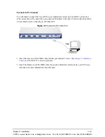
1. Plug one end of the crossover RJ-45 cable into one of the eight BRI ports on the front of the unit.
(This cable from Quintum would be the purple RJ-45 crossover cable, P/N 303-0021-00.) This
port should be configured as an NT port. See
Chapter 2: Hardware Components
for cable
pinouts if you are making your own cable.
2. Connect the other end of the crossover RJ-45 cable into the appropriate port on the PBX. (If
another cable or adapter is required, see
Chapter 2: Hardware Components
for RJ-45 crossover
pinout information.)
Connect to Trunk Interface - PSTN
NOTE:
When the Tenor is software configured as a TE device (connecting to an NT1), termina-
tion is enabled (default) when making a point-to-point connection between the TE port
and the NT1. If other TE devices are sharing the bus of the Tenor going to the NT1, termi-
nation on the TE port should be disabled. See the
Command Line Interface Guide
for con-
figuration information.
Adjacent port pairs (i.e., 1/2, 3/4, etc.) are configured by default not to connect to each other (Power
OffBypass) when the unit is turned off, or when the unit is in Offline mode. You should set Power-
OffBypass to 1 when connecting one of the lines to a PBX, and its adjacent pair to the PSTN. This
will ensure connectivity between the PSTN and PBX when the unit is turned off or when in offline
mode. However, if you have adjacent port pairs that are connected to similar devices (i.e., both
going to PSTN), you do not want the two ports to be connected to each other in case of power off or
offline, and you should set the PowerOffBypass = 0. Each pair of ports (1/2, 3/4, 5/6 and 7/8) have
their own online/offline and power off bypass control. See the
Configuration Manager
online help
or the
Command Line Interface (CLI)
guide for specific configuration information.
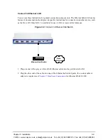
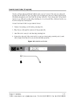
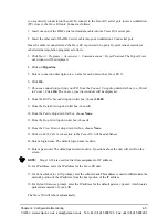
Figure 3-5
Connect to Trunk Interface
1. Plug one end of the straight through RJ-45 cable (P/N 303-5009-00) into one of the eight BRI
ports on the front of the unit. The cable from Quintum would be the green RJ-45 cable. This port
should be configured as a TE port. See
Chapter 2: Hardware Components
for cable pinouts if
you are making your own cables, or if you wish to attach the table to a punch down block.
PSTN
Patch Panel
RJ-45
Insert ports 1-8
VoIPon www.voipon.co.uk [email protected] Tel: +44 (0)1245 808195 Fax: +44 (0)1245 808299


