Section VII - Compressor Fluids
Quincy Compressor
®
- QSB/T
™
37
Lubrication
Most Quincy Compressors are equipped with a positive
displacement fluid pump mounted to the compressor and
directly driven by one of the rotors. Fluid is circulated
through the cooler, fluid filter, and into the compressor.
In the compressor, fluid is diverted through internal
passages to ensure positive lubrication of the bearings and
shaft seal. The remainder of the fluid is injected at the
beginning stage of the compression cycle to seal
clearances and to cool and lubricate the rotors. Models
not equipped with a fluid pump use pressure differential
to circulate the fluid. Positive pressure maintained in the
reservoir forces the fluid throughout the machine.
Each Quincy compressor is filled at the factory with the
correct amount of one of the synthetic fluid listed in the
Fluid Specifications. Mineral oil can be requested and
used in specific applications. The use of other brands or
types of fluid may reduce the design life of the
compressor or cause problems with filtration or carryover.
Consult the Quincy Service Department before changing
brands of fluid.
Fluid Level
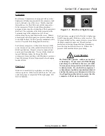
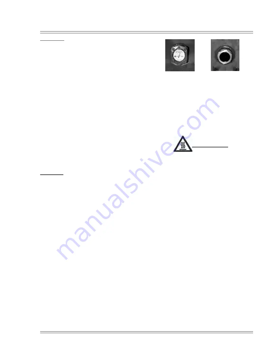
Fluid level is monitored by a sightglass or a dial gauge
while in operation. Fluid level should be in the “run” area
on the dial gauge or completely fill the sight gauge. DO
NOT OVERFILL.
Figure 1-1. Fluid Level Sight Gauges
Each unit comes equipped with a fluid level sight gauge,
fluid fill opening, and a fluid drain in the reservoir. The
fill plug is drilled to allow some pressure to escape before
the plug is completely removed. Should you hear
pressurized air venting through the hole, immediately
screw the plug back into the reservoir. Relieve the
pressure in the machine before proceeding.
CAUTION!
Hot fluid under pressure could cause death or
serious injury. Do not remove the fluid fill plug
and attempt to add fluid to the reservoir while
the compressor is in operation or when the system
is under pressure. Be sure that the compressor’s
red mushroom stop button is pushed in and locked
and that the main power disconnect switch is in
the off position and locked out to assure that the
compressor will not start automatically.
Содержание QSB Series
Страница 2: ......
Страница 9: ...Section I General Quincy Compressor QSB T 5 MODEL IDENTIFICATION...
Страница 21: ...Quincy Compressor QSB T 17 THIS PAGE INTENTIONALLY LEFT BLANK...
Страница 27: ...Quincy Compressor QSB T 23 THIS PAGE INTENTIONALLY LEFT BLANK...
Страница 71: ...Quincy Compressor QSB T 67 THIS PAGE INTENTIONALLY LEFT BLANK...
Страница 72: ...Appendix A Dimensional Drawings 68 Quincy Compressor QSB T QSB 15 50 HP air cooled...
Страница 73: ...Appendix A Dimensional Drawings Quincy Compressor QSB T 69 QSB 15 50 HP water cooled...
Страница 74: ...Appendix A Dimensional Drawings 70 Quincy Compressor QSB T QST 15 50 HP air cooled 120 gallon tank...
Страница 75: ...Appendix A Dimensional Drawings Quincy Compressor QSB T 71 QST 15 50 HP water cooled 120 gallon tank...
Страница 76: ...Appendix A Dimensional Drawings 72 Quincy Compressor QSB T QST 15 50 HP air cooled 200 gallon tank...
Страница 77: ...Appendix A Dimensional Drawings Quincy Compressor QSB T 73 QST 15 50 HP water cooled 200 gallon tank...

