Table of Contents
Quincy Compressor
®
- QSB/T
™
Standard Warranty .............................................................................................................................................................. 1
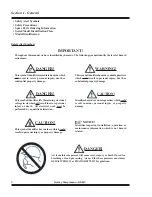
Safety Alert Symbols ......................................................................................................................................................... 2
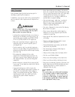
Safety Precautions .............................................................................................................................................................. 3
Spare Parts Ordering Information ....................................................................................................................................... 4
Serial/Model Identification Plate ........................................................................................................................................ 4
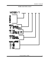
Model Identification ........................................................................................................................................................... 5
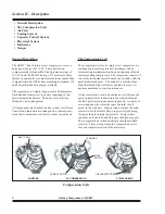
General Description ............................................................................................................................................................ 6
The Compression Cycle ..................................................................................................................................................... 6
Air Flow ............................................................................................................................................................................. 7
Cooling System .................................................................................................................................................................. 7
Capacity Control System ................................................................................................................................................. 8-9
Electrical System .............................................................................................................................................................. 10
Indicators .......................................................................................................................................................................... 11
Gauges .............................................................................................................................................................................. 11
Receiving ......................................................................................................................................................................... 12
Moving the Unit to the Installation Site ........................................................................................................................... 12
Location ........................................................................................................................................................................... 13
Piping Connections .......................................................................................................................................................... 14
Relief Valves .................................................................................................................................................................... 14
Pressure Vessels ............................................................................................................................................................... 14
Electrical .......................................................................................................................................................................... 15
Guards .............................................................................................................................................................................. 15
Manual Vent and Shutoff Valves ..................................................................................................................................... 15
Water and Sewer Facilities at the Installation Site ........................................................................................................... 16
Compressor Rotation ........................................................................................................................................................ 16
Fan Rotation ..................................................................................................................................................................... 16
Section IV - Operating Procedures
Prior To Starting ............................................................................................................................................................... 18
Starting the Compressor ................................................................................................................................................... 18
Stopping the Compressor - Normal Operation ................................................................................................................. 19
Stopping the Compressor - Emergency Operation ........................................................................................................... 19
Electronic Control Operation (optional) ...................................................................................................................... 19-21
Содержание QSB Series
Страница 2: ......
Страница 9: ...Section I General Quincy Compressor QSB T 5 MODEL IDENTIFICATION...
Страница 21: ...Quincy Compressor QSB T 17 THIS PAGE INTENTIONALLY LEFT BLANK...
Страница 27: ...Quincy Compressor QSB T 23 THIS PAGE INTENTIONALLY LEFT BLANK...
Страница 71: ...Quincy Compressor QSB T 67 THIS PAGE INTENTIONALLY LEFT BLANK...
Страница 72: ...Appendix A Dimensional Drawings 68 Quincy Compressor QSB T QSB 15 50 HP air cooled...
Страница 73: ...Appendix A Dimensional Drawings Quincy Compressor QSB T 69 QSB 15 50 HP water cooled...
Страница 74: ...Appendix A Dimensional Drawings 70 Quincy Compressor QSB T QST 15 50 HP air cooled 120 gallon tank...
Страница 75: ...Appendix A Dimensional Drawings Quincy Compressor QSB T 71 QST 15 50 HP water cooled 120 gallon tank...
Страница 76: ...Appendix A Dimensional Drawings 72 Quincy Compressor QSB T QST 15 50 HP air cooled 200 gallon tank...
Страница 77: ...Appendix A Dimensional Drawings Quincy Compressor QSB T 73 QST 15 50 HP water cooled 200 gallon tank...


