Page 51 of 69
6-2 LINKAGE ASSEMBLY
No. Bag#
Description
Qty
1 6
2.3 Long Ball End
26
2
6
2.3 Medium Ball End
4
3 6
2.3x25mm
Rod
2
4 6
2.3x35mm
Rod
3
5 6
2.3x45mm
Rod
2
6 6
2.3x50mm
Rod
2
7 6
2.3x80mm
Rod
2
8 6
2.3x100mm
Rod
2
Coding the Rod Assembly:
All the Linkage should be assembled with dimensions measured center to center and
coded as followings:
No. Rod
Description Link Ball End used
Center to Center Qty
1 2.3x25mm
Rod
Medium 42
mm
2
2 2.3x35mm
Rod
Long 58
mm
3
3 2.3x45mm
Rod
Long 70
mm
2
4 2.3x50mm
Rod
Long 82
mm
2
5 2.3x80mm
Rod
Long 105
mm
2
6 2.3x100mm
Rod
Long 127
mm
2
The lengths of
linkages are used for
reference only. Final
adjustments might
need to be made
after setup.
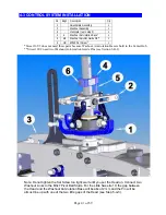
Note: Look close to a ball end; you will see one side is different from the other. One has a round
marked on it. The other is just plain. When installing a ball link into a pivot ball stud (or a shim
ball) the side with a round should face away from a ball stud (or shim ball.)
Содержание Little Sweetie 10 Pro
Страница 1: ...Page 1 of 69...
Страница 7: ...Page 7 of 69 REQUIRED TOOLS Dremel Tools and Sandpapers would be helpful for building...
Страница 8: ...HARDWARE OPTIONAL ACCESSORIES GLUES AND THREAD LOCK COMPOUNDS RADIO MOUNTING ACCESSORIES Page 8 of 69...
Страница 13: ...Page 13 of 69 ASSEMBLY SECTION 1 REAR FRAMES Bag 1...
Страница 17: ...Page 17 of 69 SECTION 2 MAIN FRAMES Bag 2...
Страница 25: ...Page 25 of 69...
Страница 27: ...Page 27 of 69...
Страница 28: ...Page 28 of 69...
Страница 37: ...Page 37 of 69...
Страница 42: ...SECTION 5 A ROTOR HEAD for Little Quickie 10 Bag 5 Page 42 of 69...
Страница 44: ...Page 44 of 69...
Страница 53: ...Page 53 of 69...
Страница 54: ...Page 54 of 69...
Страница 55: ...Page 55 of 69...
Страница 59: ...Picture 3 Swash Up Picture 4 Head Picture 5 Tail Center Picture 6 Tail Positive Thrust Page 59 of 69...


