background image


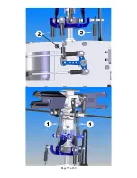
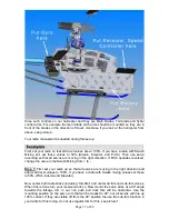
SECTION 5-A: ROTOR HEAD for Little Quickie 10 

Bag 5 


Page 42 of 69

Содержание Little Sweetie 10 Pro

Страница 1: ...Page 1 of 69...

Страница 2: ...1 PART LIST 12 SECTION 1 REAR FRAMES 13 SECTION 2 MAIN FRAMES 17 SECTION 3 TAIL ASSMEBLY 32 SECTION 4 CONTROL SYSTEM 39 SECTION 5 A ROTOR HEAD FOR LITTLE SWEETIE 10 42 SECTION 5 B ROTOR HEAD FOR SWEET...

Страница 3: ...ime and the efficiency increase significantly day by day We believe so much in our electric helicopters that we have given out for reviews to our fellow hobbyists EP kits of four different motors and...

Страница 4: ...4811 Fax 610 282 4816 Websites http www hhiheli com http www quickheli com http www giantscaleplanes com E mail hhi fast net Office Hours Mon Fri 8 30 6 00 Sat 8 30 1 30 Eastern Daylight Time Technica...

Страница 5: ...sign allows ease of setup with fewer moving parts EMS demonstrates overall design simplicity and represents the future of helicopter technology 5 Control Linkages The control linkages provided with th...

Страница 6: ...nization that provides services to model aircraft pilots As an AMA member you will receive a monthly magazine entitled Model Aviation as well as a liability insurance plan to cover against possible ac...

Страница 7: ...Page 7 of 69 REQUIRED TOOLS Dremel Tools and Sandpapers would be helpful for building...

Страница 8: ...HARDWARE OPTIONAL ACCESSORIES GLUES AND THREAD LOCK COMPOUNDS RADIO MOUNTING ACCESSORIES Page 8 of 69...

Страница 9: ...CCESSORIES 3MM FLYBAR STIFFENERS HHI 402 30 SIZE SKID STOPS HHI 200 AVAILABLE IN COLORS SERVO ARM SET LANDING GEAR DAMPENERS HHI 2004 BASE LOAD ANTENNA HHI 53 AVAILABLE IN BLUE GOLD PURPLE AND IN 40 5...

Страница 10: ...across larger surface area 3mm 4mm 20 pcs in a package 8 pcs in a package BLACK HHIM11100B WITHOUT BLUE HHIM11103 HHIM11108 GOLD HHIM11101 HHIM11106 GREEN HHIM11100G PURPLE HHIM11100 HHIM11105 WITH RE...

Страница 11: ...helicopter they can be the single most important component that contributes to proper function of the helicopter Due to the nature of EMS collective we suggest the use of digital servos to enhance an...

Страница 12: ...losing parts No with means that part is not included in the kit Colors of the drawings for parts in this manual may look differently from the real parts in the kit Check out our website for latest inf...

Страница 13: ...Page 13 of 69 ASSEMBLY SECTION 1 REAR FRAMES Bag 1...

Страница 14: ...stall Counter Gear Bearing Block Upper one with the Flange facing down Install Pulley Gear Plate No 6 Insert Pulley Gear Lock Pin No 7 Apply JP Weld around the pin Install Pulley Gear and retain with...

Страница 15: ...1 2 Servo 1 3 HB M2 5x14 Cap Head Bolt 4 4 HB M2 5 Locknut 4 5 HB Fixing Plate 2 HB Hardware Bag Note Servos are not included in the kit If the servos come with anti vibrating rubber insert them on t...

Страница 16: ...me 1 6 HB M3x8 Cap Head Bolt 8 3 Step 1 1 1 7 HB M3 Locknut 4 4 1 Boom Holder 2 8 HB M3x7 Flat Washer 8 Do not tighten four nuts at Tail Boom Holder Halves too tight since you are going to install the...

Страница 17: ...Page 17 of 69 SECTION 2 MAIN FRAMES Bag 2...

Страница 18: ...HAFT BEARINGS No Bag Description Qty 1 Frame Main Frame 2 2 2 5x10x4 Flanged Bearing 2 Note The holes on the frames are designed for push fit feature Sometime you may have to sand them a little bit be...

Страница 19: ...LY No Bag Description Qty 1 Right Frame from Step 2 1 1 2 Servo 2 3 HB M2 5x14 Cap Head Bolt 8 4 HB M2 5 Locknut 8 5 HB Fixing Plate 4 Note Servos are not included in the kit If the servos come with a...

Страница 20: ...them on the servos first 2 4 INNER ELEVATOR CONTROL ARM SUBASSEMBLY Note Elevator Control Shaft is designed to fit tightly in M5x11x4 Flange Bearings on the Upper Frames So before you do the following...

Страница 21: ...y No Bag Description Qty 1 Step 2 2 1 6 HB M3x16 Cap Head Bolt 1 2 Step 2 4 1 7 HB M3x5 Set Screw 1 3 2 Outer Elevator Control Arm 1 8 HB M3x5x3 Spacer 2 4 2 Right Aileron Control Lever 1 9 HB M3x7 Pi...

Страница 22: ...weetie 10 use M4x6 Cap Head Bolts Note it is very important to use a Dial Indicator to check the run out of the Pinion Gear shaft Most of the vibration problems come from this The run out should be no...

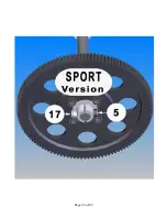
Страница 23: ...e 23 of 69 2 7 MAIN GEAR ASSEMBLY No Bag Description Qty 1 2 Main Gear 1 2 2 Main Gear Hub 1 3 HB M3x 6 Cap Head Bolt 4 Sport version is shown on the drawing Pro version may look a little bit differen...

Страница 24: ...4 16 Frame Motor Frame Doubler 1 5 HB M3x18 Cap Head Bolt 5 17 HB M3 Locknut 2 6 2 Main Shaft Bearing Block 1 18 Main Gear Assy Step 2 7 1 7 Frame Anti rotation Guide 1 19 2 Lower Main Shaft Collar 1...

Страница 25: ...Page 25 of 69...

Страница 26: ...nter sunk for nicer finish Slide the Main Gear Assembly in insert the Main Shaft through the Main Shaft Bearing Blocks Then secure the Gear with one M3x18 Cap Head Bolt and one M3 Locknut For Pro vers...

Страница 27: ...Page 27 of 69...

Страница 28: ...Page 28 of 69...

Страница 29: ...Bolt 4 12 HB M3x5x3 Spacer 2 6 HB M3x8 Cap Head Bolt 18 HB M3x4 Pivot Ball Stud 1 7 HB M3 Locknut 1 Attach the Left Side Assembly and the Right Side Assembly together secure them with Cap Head Bolts...

Страница 30: ...Cap 4 7 2 10 M3 Locknut 4 4 2 10 M2 5x6 Self Tapping Screws 4 Drill 4 holes in the Landing Gear Struts with a 3mm drill bit with a spacing of 63 5mm Install the Landing Gear Skids into the Struts Appl...

Страница 31: ...re them with four M3x12 Cap Head Bolts Note It is recommended to use Landing Gear Dampener to reduce vibration See Other Hardware Optional Accessories to make order Landing Gear Dampener is installed...

Страница 32: ...Page 32 of 69 SECTION 3 TAIL ASSEMBLY Bag 3 3 1 TAIL PULLEY GEAR SUBASSEMBLY No Bag Description Qty 1 3 Tail Output Shaft 1 2 HB M3x5 Set Screw 1 3 3 Tail Pulley Gear 1 4 3 Tail Gear Side Plate 1...

Страница 33: ...x1 Spacer 4 5 In Box Tail Boom 1 14 HB M3x16 Cap Head Bolt 1 6 In Box Timing Belt 1 15 HB M3 Locknut 1 7 HB M3x6 Cap Head Bolt 6 16 3 1 Tail Pulley Gear Subassy 1 8 3 Tail Case Cross Member 1 17 HB M2...

Страница 34: ...Member If your Tail Cross Member is long enough 16mm you do not need the spacer for it Normally you just need one M3x5x1 Spacer between the Tail Pitch Control Lever and Tail Pitch Lever Mount but you...

Страница 35: ...10 Cap Head Bolt 2 16 HB M3x30 Cap Head Bolt 2 8 HB M3x5 Set Screw 1 18 3 Electric Tape 1 9 3 Vertical Fin Mount A 1 Carbon Fin Set is also available for option Little Sweetie 10 uses two M3x16 Cap He...

Страница 36: ...After installing all the parts as shown above slide this subassembly on the output shaft then secure it with one M3x5 Set Screw Now put the Ball Links on the Shim Balls Page 36 of 69...

Страница 37: ...Page 37 of 69...

Страница 38: ...lling the timing belt Turn the Tail assembly so that the Tail Output Shaft pointing upward put the belt onto the Transmission then twist the Tail Assembly 90o to the right Make sure the belt not too t...

Страница 39: ...69 SECTION 4 CONTROL SYSTEM Bag 4 4 1 SWASHPLATE ASSEMBLY No Bag Description Qty 1 4 Swashplate Complete 1 2 HB M3x7Pivot Ball Stud 6 3 HB M3x 7Flat Washer 4 4 HB M2X4 Phillips Screws 7 5 4 Anti rota...

Страница 40: ...SEMBLY No Bag Description Qty No Bag Description Qty 1 4 Washout Base 1 5 4 M3x5 Set Screw 2 2 4 Washout Arm 2 6 HB M3x7Pivot Ball Stud 2 3 4 Washout Link 2 7 HB M3x10 Cap Head Bolt 2 4 4 Washout Link...

Страница 41: ...n Base 1 5 4 5 Washout Anti Rot Guide Pin 1 6 HB M3x5 Set Screw 1 Sweet 16V2 need two Washout Anti rotation Guide Pins see Section 5 B 2 Note Do not tighten the Set Screw too tight wait until you put...

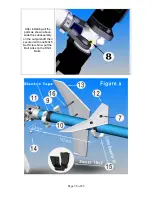
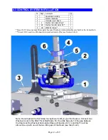
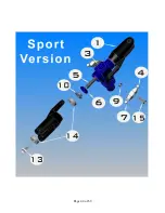
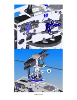
Страница 42: ...SECTION 5 A ROTOR HEAD for Little Quickie 10 Bag 5 Page 42 of 69...

Страница 43: ...3x7 Pivot Ball Stud 2 16 HB 5x7x2 Spacer 2 8 HB M3x8 Cap Head Bolt 4 17 HB M9x13x1 45 Thrust Bearing Spacer 2 9 HB M3X5X3 Spacer 2 18 HB M2x4 Phillips Screw 4 Sport version Pitch Arms is built in the...

Страница 44: ...Page 44 of 69...

Страница 45: ...r 2 7 5 Fly Bar Control Arm 2 14 5 Short Ball End 4 15 Epoxy Glue JP 1 Screw two Short Ball Ends until they hit each other There are two holes in the paddles For regular setup use the hole that is fur...

Страница 46: ...TION No Bag Description Qty 1 Fly Bar Seesaw Assembly 1 2 Helicopter up to step 4 1 3 HB M3x20 Cap Head Bolt 1 4 HB M3 Locknut 1 Install the Head Assembly into the Main Shaft and then secure it by one...

Страница 47: ...Hiller Arm It works the same please see the figure for installation Note Some Center Hubs are designed for one O ring each side If this is your case use one O ring each side The beveled edge of the T...

Страница 48: ...rotation Pin 2 8 In box 4mm Standard Flybar 1 16 Epoxy Glue JP Weld 1 There are two holes in the paddles For regular setup use the hole that is further from the letter Quick on the paddles Although th...

Страница 49: ...Page 49 of 69 5 B 3 ROTOR HEAD INSTALLATION No Bag Description Qty 1 Fly Bar Seesaw Assembly 1 2 Helicopter up to step 4 1 3 HB M3x20 Cap Head Bolt 1 4 HB M3 Locknut 1...

Страница 50: ...2 5 6 Rudder Pushrod Guide Insert 2 6 HB Shim Ball 1 7 HB M2x8 Phillips Screw 1 8 Servo Arm 1 9 M3 Servo Phillips Screw 1 10 6 2 3 Long Ball End 2 11 CA Glue 1 The length of the Rudder Rod measured f...

Страница 51: ...l End used Center to Center Qty 1 2 3x25mm Rod Medium 42 mm 2 2 2 3x35mm Rod Long 58 mm 3 3 2 3x45mm Rod Long 70 mm 2 4 2 3x50mm Rod Long 82 mm 2 5 2 3x80mm Rod Long 105 mm 2 6 2 3x100mm Rod Long 127...

Страница 52: ...ty 1 2 3x25mm Rod Assembly 2 7 Helicopter up to step 6 1 1 2 2 3x35mm Rod Assembly 3 8 Servo Arm 3 3 2 3x45mm Rod Assembly 2 9 HB Shim Ball 6 4 2 3x50mm Rod Assembly 2 10 HB M2x8 Phillips Screw 6 5 2...

Страница 53: ...Page 53 of 69...

Страница 54: ...Page 54 of 69...

Страница 55: ...Page 55 of 69...

Страница 56: ...4 Gyro 1 5 Speed Controller 1 6 Battery for Receiver 1 7 Main Battery 8 Battery Connector 1 Before setting up the radio you have to install the receiver gyro speed controller and batteries for your h...

Страница 57: ...rsed change the value in the Swash Mixing from to Step 1 First set your radio up so that all servos are moving in the right direction and adjust all travel values to 100 If you have a radio with Swash...

Страница 58: ...arms to the Swashplate connect to the two longer pivot studs if all four are the same length then any two will do The next step is to adjust the length of the linkage rod between the Washout Arm and...

Страница 59: ...Picture 3 Swash Up Picture 4 Head Picture 5 Tail Center Picture 6 Tail Positive Thrust Page 59 of 69...

Страница 60: ...Position Normal Flying Aerobatic Up 100 10o 10o Center 50 5o 0o Down 0 3o 10o Throttle Curve Setup Fuel Electric non governor mode Collective Position Normal Flying Aerobatic Normal Flying Aerobatic...

Страница 61: ...are looking for Your goal is to achieve a constant head speed once the helicopter is airborne If you ad pitch climb you need to ad power throttle to compensate for the added resistance a higher blade...

Страница 62: ...d off 4 4 6 Canopy Grommet 4 5 HB M3x6 Cap Head Bolt 4 6 HB M3x12 Cap Head Bolt 4 Install the 4 Canopy Standoff using 4 M3x6 Cap Head Bolts Put the Canopy on the helicopter mark the right positions fo...

Страница 63: ...the helicopter WARNINGS Do not operate helicopters in rainy windy or snowy condition Operate helicopter in a safe zone away from crowds traffic or distractions Use the proper batteries to prevent dam...

Страница 64: ...he pushrods that connect to the main rotor blade pitch arm Out of track Repeat steps a to c until the blades are in track Trimming Most of new built helicopters are unstable But if you trim your helic...

Страница 65: ...b Check the main rotor fore aft and left right cyclic to make sure the main rotor is following to your cyclic command before taking off Make sure the helicopter nose will swing in your desired directi...

Страница 66: ...ground since in an emergency situation you can drop the throttle and collective quickly without making any big damage 4 8 inches e Stand behind the helicopter so you can watch the nose of the helicop...

Страница 67: ...ce you have mastered hovering fight a Let s begin the exercise of changing positions by practice moving the helicopter to the left or right slowly from 60 inches 1 5 m above the ground Hovering at 60...

Страница 68: ...he previous step start using some tail rotor control to make the helicopter point slightly to the left or right as you fly it to the left or right Keep practicing the figure eight path as shown below...

Страница 69: ...ASHED Turn off everything and check the helicopter immediately If any item is damaged replace the damaged parts to ensure safe operation Do not try to glue any broken or damaged plastic or carbon part...

Отзывы: