


LPWA Module Series
BG95 Hardware Design
BG95_Hardware_Design 47 / 80
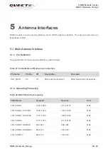
3.11. PCM* and I2C* Interfaces
BG95 provides one Pulse Code Modulation (PCM) digital interface and one I2C interface. The following
table shows the pin definition of the two interfaces which can be applied on audio codec design.
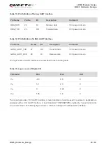
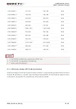
Table 16: Pin Definition of PCM and I2C Interfaces
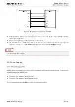
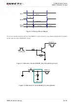
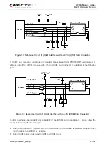
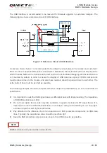
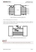
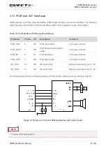
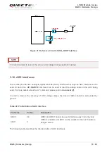
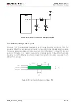
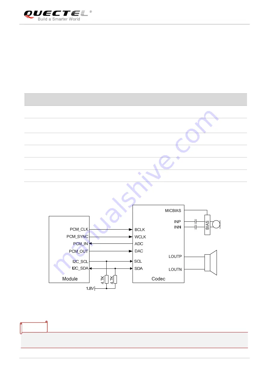
The following figure shows a reference design of PCM and I2C interfaces with an external codec IC.
Figure 18: Reference Circuit of PCM Application with Audio Codec
“*” means under development.
Pin Name
Pin No.
I/O
Description
Comment
PCM_CLK*
4
DO
PCM clock output
1.8V power domain
PCM_SYNC* 5
DO
PCM frame synchronization
output
1.8V power domain
PCM_IN*
6
DI
PCM data input
1.8V power domain
PCM_OUT*
7
DO
PCM data output
1.8V power domain
I2C_SCL*
40
OD
I2C serial clock
Require external pull-up to 1.8V
I2C_SDA*
41
OD
I2C serial data
Require external pull-up to 1.8V
NOTE


