Bit Error Rate Tester | BERT 1005
Quantifi Photonics Ltd.
Version
2.04
44
Error detection
The ED channel inputs must be connected to the signal for the error detectors to work properly. Follow
the suggested configuration and meet proper torquing requirements for RF cables and bulkheads to
guarantee error free operation.
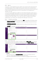
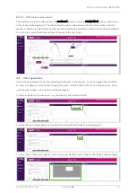
For error analysis, an error rate vs. time plot is displayed, showing the error rate trend. The graph is a
strip chart that displays the BER count of the last 20 seconds, with one data point per second. The strip
chart can be used to monitor either the total error count (accumulated BER mode) or the instantaneous
error count (error rate calculated over the last one second). The time plot tool can be very helpful in
isolating repetitive errors that occur at low frequencies, error bursts, and other thermal cycling or
changing conditions that can affect digital communications.
8.3.1
Error detection indicators
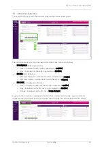
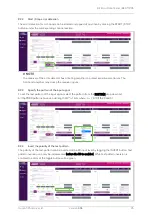
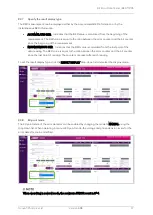
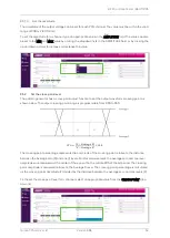
The following indicators are used to indicate the data, error, and operation status:
•
RESULT DISPLAY: Display the result type of the BER measurement (see section 8.3.7).
•
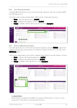
POINT: The current ED point mode status (see section 8.3.8 for more information).
•
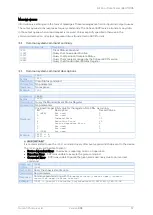
DATA OK: The presence of valid data at the input of the ED circuits.
o
Green indicator
–
Indicates that data is present at the ED input.
o
Gray indicator
–
Indicates that no data is present at the ED input.
•
LOCK: The lock status of the input data of the internal PLL (phase-locked loop). PLL must be
locked for the bit counter to start measuring BER.
o
Green indicator
–
Indicates that the PLL is locked to the ED input pattern.
o
Red indicator
–
Indicates that the PLL is not locked to the ED input pattern. Check the input
pattern and force a re-sync to lock the PLL before attempting to start the BER counter.
•
BER (Bit Error Rate): Current BER of the incoming data pattern.
•
ERROR: Number of error bits since the start of the ED counter.
•
BITS: Number of incoming bits counted since the start of the ED counter.
•
ELAPSED TIME: Elapsed time in seconds measured since the start of the ED counter.
If the ERROR count exceeds the maximum allowable number of errors for the error detector,
the error detector will automatically stop, and the ERROR field will turn red. The maximum
number of errors for the ED mode is 2
64
-1.
Содержание BERT 1005 Series
Страница 1: ......
Страница 6: ...Bit Error Rate Tester BERT 1005 Quantifi Photonics Ltd Version 2 04 6 Service and repairs 93 ...
Страница 94: ...2 04 ...

