Table of Contents
4
3.3.3
LAN0 and LAN1 Ethernet interface connectors ..................................... 24
3.3.4
VGA interface connector ..................................................................... 25
3.3.5
Reset button ...................................................................................... 25
3.3.6
Status LEDs ....................................................................................... 26
3.3.7
Grounding screw (M4) with lock washers ............................................. 26
3.4
Top view .......................................................................................... 27
3.4.1
CompactFlash card slot ...................................................................... 27
3.5
Left and right side view ..................................................................... 28
3.6
Rear view ......................................................................................... 30
3.7
Single-board computer ...................................................................... 31
3.8
Accessing internal components ........................................................... 31
3.8.1
Configuration of the RS422/RS485 port ............................................... 31
3.8.2
Configuration of the PROFIBUS-DP slave interface ............................... 33
3.8.3
Replacing the lithium battery .............................................................. 33
4.
Wiring and installation ............................................... 35
4.1
Connecting the system to the power supply ........................................ 36
4.1.1
DC Power Plug ................................................................................... 36
4.1.2
Connecting to the DC Power Supply .................................................... 37
4.2
Mounting the system to a subframe or panel ....................................... 39
4.3
Pin assignments ................................................................................ 43
4.3.1
Ethernet interfaces (LAN0 and LAN1) .................................................. 43
4.3.2
USB interfaces ................................................................................... 43
4.3.3
RS232 (COM1) ................................................................................... 43
4.3.4
VGA port (VGA) ................................................................................. 44
4.3.5
DC Power Connector .......................................................................... 44
4.3.6
Optional interfaces ............................................................................. 45
4.3.6.1
RS422/RS485 (COM2) ................................................................ 45
4.3.6.2
RS232 (COM2) .......................................................................... 46
4.3.6.3
PROFIBUS-DP slave ................................................................... 46
Содержание Imagechecker Q.400PD
Страница 1: ...Imagechecker Q 400PD Hardware Manual www qvitec de Erkennen was möglich ist ...
Страница 7: ......
Страница 8: ...Chapter 1 Introduction ...
Страница 16: ...Chapter 2 Scope of delivery ...
Страница 18: ...Chapter 3 Product description ...
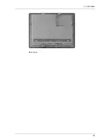
Страница 20: ...3 1 All views 19 Rear view ...
Страница 31: ...Product description 30 3 6 Rear view Rear of the GN10 Rear of the GN07 3 5 1 2 2 4 2 2 2 2 2 2 3 1 2 2 2 2 ...
Страница 36: ...Chapter 4 Wiring and installation ...
Страница 51: ......
Страница 52: ...Chapter 5 Technical data ...
Страница 57: ...Technical data 56 GN10 GN12 ...
Страница 58: ...5 3 Dimensions 57 GN15 5 3 2 Rear and Right Side Views GN07 ...
Страница 59: ...Technical data 58 GN10 GN12 ...
Страница 60: ...5 3 Dimensions 59 GN15 ...
Страница 61: ......
Страница 64: ...63 Record of changes Manual No Date Description of Changes MANHWQPCPD13AE June 2013 First edition ...


