6
Assembly and installation manual
QIM/QDB Mixer Series
QIM/QDB-M01
HOW TO INSTALL THE PIPING
GENERAL
This section provides some do’s and do not’s of piping which will aid in obtaining the maximum
efficiency and service from your pump. Piping should be independently supported at both the
suction inlet and discharge outlet. Care should be taken that piping is properly aligned and does
not put any strain on the pump casing. The piping should have as few bends as possible.
SUCTION PIPING
The suction piping should be short and follow a direct route with a minimum number of elbows
and fittings. Elbows should be located as far as possible from the suction inlet to prevent head
loss due to increased friction. Excessive friction losses in the suction line could result in pump
cavitation, causing poor performance, noise, vibration, damage to equipment and possible
damage to fluid.
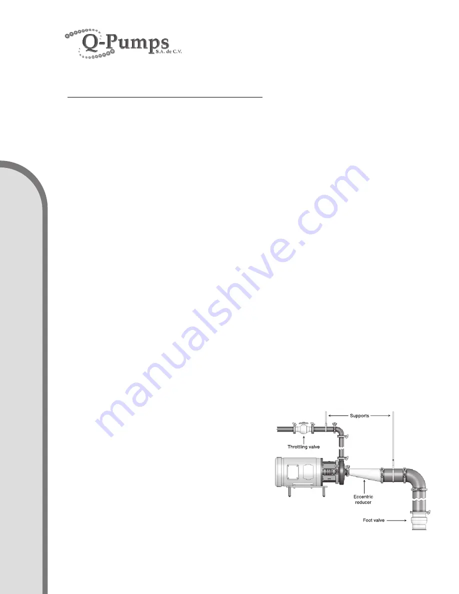
Whenever possible the diameter of the piping at the suction inlet should be increased in size, an
eccentric tapered reducer should be used instead of a concentric tapered reducer to prevent
air pockets from forming and impairing pump efficiency. In turn, the eccentric reducer may be
placed at the inlet of the pump and should be positioned so the straight side is up. A horizontal
suction pipe must have a gradual rise to the pump. A high point in the suction line will form an
air pocket and prevent proper pump operation. All joints in the suction line should be air tight, to
prevent air leakage which can reduce pump capacity and efficiency.
DISCHARGE PIPING
Position of the pump discharge is preferably either vertical or top horizontal. The discharge piping
should be short and direct with a minimum number of elbows and fittings. Elbows should not be
used at the discharge outlet, as the friction encountered would be increased, resulting in head
loss. However, use of a large discharge pipe than recommended may reduce the total pump
head, but increase the pump volume, which can cause pump vibration due to overload. Use
of a discharge pipe smaller than the pump discharge outlet increases the total pump head but
decreases the volume. If a reducer is required on the outlet port of the pump and the discharge
is vertical a concentric reducer should be used. If the
discharge is horizontal an ec centric reducer should be
used and should be positioned so the straight side is
down.
LOCATING VALVES
In suction lift applications where the lift is not very
high, it may be desirable to install a foot valve, to
facilitate priming, and to prevent draining off of the
liquid back to the source. A throttling valve should
be installed in the discharge piping to provide control
pump flow rate and prevent motor overload.
IN
ST
ALL
ATIO
N


