14
Assembly and installation manual
QIM/QDB Mixer Series
QIM/QDB-M01
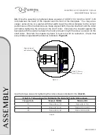
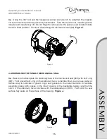
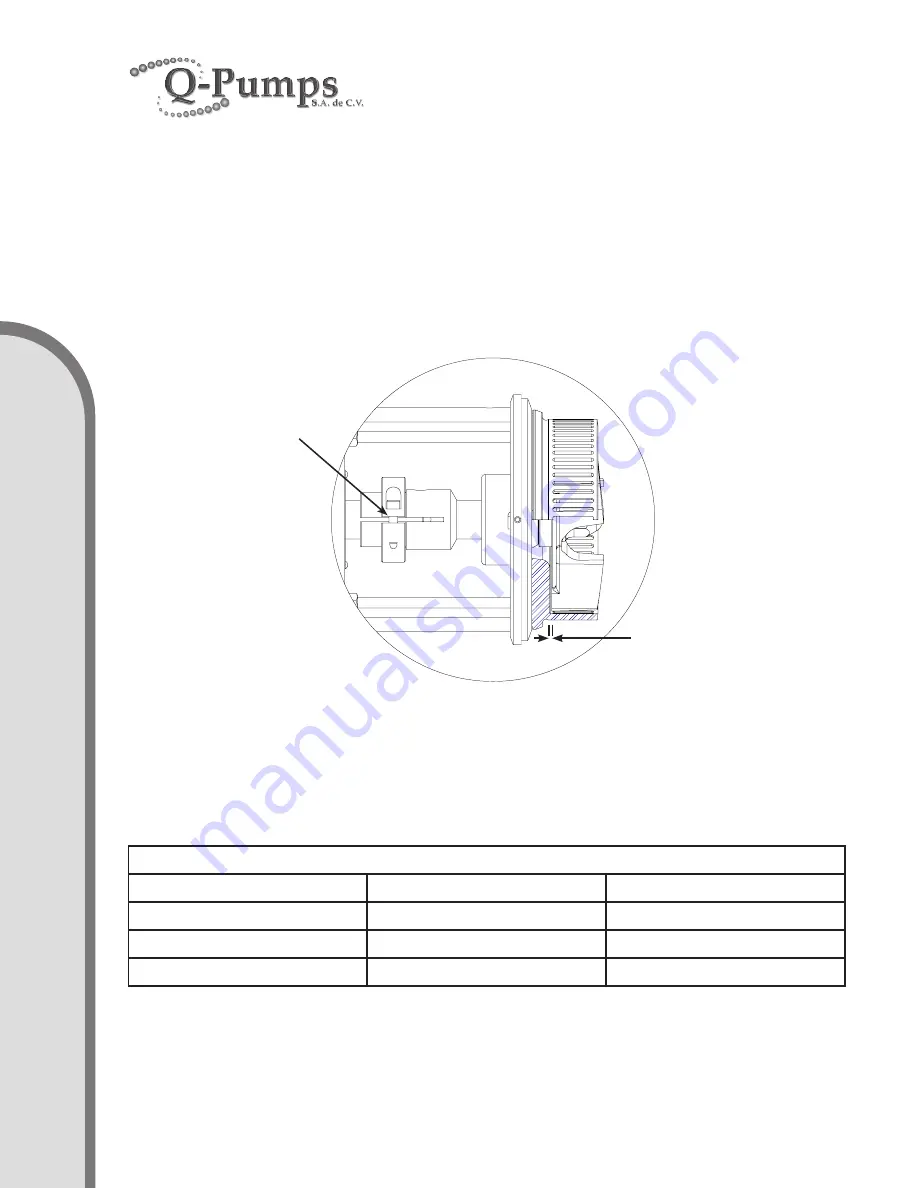
3d. Once the assembly is tightened place a spacer of 0.060” (1.53 mm) thru 0.070” (1.78
mm) between the back of the impeller and the front of the backplate. You may use a
caliper, some shims or a washer with that width to set the critical distance for the correct
performance of the mechanical seal. Keep aligned both, the stub shaft slot and the collar
slot before tightening the screws on the shaft collar. Compress the impeller against the
backplate with the spacer between them and proceed to tight the screw or screws on the
shaft collar. Now turn the impeller by hand, it must turn with no restriction. Check that
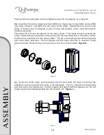
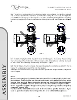
every blade is separated the distance indicated. Figure H.
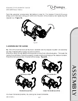
Use the torque values for tightening the collar screws indicated in the Chart 2.
f
L
Figure H.
Chart 2.
Align stub shaft
and collar slots
0.060” (1.53 mm)
0.070” (1.78 mm)
Chart 2 – Torque values for tightening the stub shaft collar Allen screws
Torque ft-lb
Models NEMA
Models IEC
15
Frame 56 to 18
Frame 80 to 112
30
Frame 21 to 25
Frame 132 to 160
40
Frame 28 to 32
Frame 180 to 225
A
SS
EM
B
LY


