17
Assembly and installation manual
QIM/QDB Mixer Series
QIM/QDB-M01
Tight the assembly as previously did before in step 3c. For models 114 and 214 use a
torque of 25 ft.lb and a torque of 40 ft.lb for the rest of the models when tightening the
impeller nut. Figure M.
5. ASSEMBLING THE CASING
5a. Once the mechanical seal has been installed and the impeller-impeller nut assembly
has been tightened the casing must be mounted.
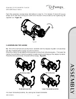
Place the casing O-ring (90A) onto the groove on the front of the backplate. Then take the
casing (1) and locate it onto the adapter, positioning the discharge at the desired location.
Place the clamp assembly (75) around the casing. Figure N.
In a lower horizontal position, the casing can be self-drainable.
Figure M.
A
SS
EM
B
LY
Vertical position
Horizontal position
Lower horizontal position
45º Inclination

