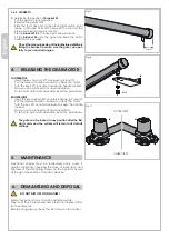
background image

6

Fig. 9

Fig. 10

B

A

C

D

90°

B

A

D

90°

min.

30÷35 mm

Fig. 11

Fig. 12

Fig. 13

T1

PR1

G1

Fig. 14


PR1

G1

S3

2 cm

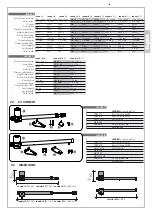
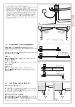
 3.4.3  OUTWARD OPENING

Your gate can be automated for opening outwards too. 

In this case the value of 

A

 dimension shall be calculated 

towards the gate center. 

See picture 9 and 10 and fit the bracket accordingly.

INNER VIEW  

OUTER VIEW

INNER VIEW  

OUTER VIEW


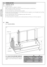
3.5  FASTENING REAR BRACKET T1 

Weld or bolt the rear 

bracket T1

 on the post, applying the 

A


and

 B

 quota calculated according to the gate hinge 

position and the motor rotation point.

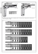
Chemical bolts can be used and must comply with the post 

features (brick, wood, steel, etc. etc.). When fixing keep a 

minimum distance of 30/35 mm from the post edge in order 

to avoid damages (see picture 11). 

-  Rear 

brackets T1

 are provided 

LH

 and 

RH

, to match to the 

according LH and RH motor  (see picture 12).

-  When fixing the operator to the rear 

bracket T1

, plug 

PR1


rotation pin downward oriented (see picture 13).


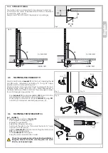
3.6  FASTENING FRONT BRACKET S3

3.6.1  LEADER TI 

To determine the position of 

bracket S3

:

-  Put the gate in closing position.

-  Release the gearmotor.

-  Extend the inox pipe arm fully.

-  Turn back the arm 2 cms. This avoids the motor to “leap 

forward” (see picture 14)

-  Affix the 

bracket S3

 to the motor slot. Plug the rotation pin 

PR1

 into the locating hole.

-  Fit the 

bracket S3

 on the gate. 

-  Keep the motor horizontal, fix or weld.


Check the manual opening of the leaf before definitively 

fixing the bracket to make sure the gate can open 

fully to your required angle.

T1 

RH

T1 

LH

Содержание LEADER 3

Страница 1: ...01_17 LEADER Gearmotor for swing gates INSTALLATION MANUAL...

Страница 2: ......

Страница 3: ...3 2 Wiring pag 03 3 2 1 Standard installation 3 2 2 Cable types and minimum thicknesses 3 3 Establishing RH and LH operator pag 04 3 4 Fastening the gearmotor pag 04 3 4 1 Vertical positioning quota 3...

Страница 4: ...24 4 TA Is built to be integrated into a machine or to be assembled with other machinery to crate a machine under provisions of 2006 42 EC Machinery Directive with reference in particular to the follo...

Страница 5: ...0 kg 2 0 m 2 5 m 3 0 m 2 0 m 2 75 m 3 50 m 80 80 80 40 40 40 LEADER TI LEADER TA Leader 4 TA Leader 4 TA 24 Leader 4 TA 115 230V 50Hz 1 2 1 7A 280W 8 F 150 C 2800 N 44 1400 rpm 110 deg 22 300 Kg 2 75...

Страница 6: ...manual release Any lawn watering devices will not wet the gearmotor from the bottom up The earth cable is properly connected Do not install onto gates on either an upward or downward slope i e that ar...

Страница 7: ...t any height from ground b If the gate is particularly light fit the gearmotor as close as possible to gate centerline 3 4 2 Horizontal positioning quota Gate leaf hinged in the center of the pillar s...

Страница 8: ...tor stroke Leader 3 TI C 300 mm Leader 4 TI C 400 mm Leader 5 TI C 500 mm If the ideal scenario of A and B is not applicable refer to the below table to determine the brackets position values are expr...

Страница 9: ...minimum distance of 30 35 mm from the post edge in order to avoid damages see picture 11 Rear brackets T1 are provided LH and RH to match to the according LH and RH motor see picture 12 When fixing th...

Страница 10: ...an proceed to manual operation To return to automatic operation invert the procedure RH OPERATOR Insert the key and turn 90 counterclockwise picture 17 Pull the release handle outwards to unlock the m...

Страница 11: ...8 24V 230V 18 22 B 3 9 13 19 23 24 39 29 30 26 34 35 31 33 3 3 40 40 40 40 43 44 44 43 1 4 5 6 7 15 16 38 37 17 36 32 22 A LEADER TI...

Страница 12: ...12 15 16 11 23 24 39 29 10 20 3 3 40 40 40 40 43 44 38 37 44 43 17 36 8 21 14 24V 26 22 A LEADER TA Proteco S r l Via Neive 77 12050 CASTAGNITO CN ITALY Tel 39 0173 210111 Fax 39 0173 210199 info prot...

Отзывы: