


LEADER TA
2
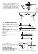
170
190
(24V)
Leader 3 TI
= 665 -
Leader 4 TI
= 765 -
Leader 5 TI
= 865 mm
Leader 3 TI
= 965 -
Leader 4 TI
= 1165 -
Leader 5 TI
= 1365 mm
Leader 4 TA
= 885
170
190
(24V)
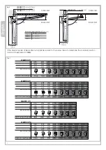
Leader 3 Leader 4 Leader 5
230V ~ 50Hz 230V ~ 50Hz 230V ~ 50Hz
1,2 - 1,7A
1,2 - 2A
1,2 - 1,7A
280W 280W 280W
8µF 8µF 8µF
150°C 150°C 150°C
2800 N
2800 N
2800 N
44 44 44
1400 rpm
1400 rpm
1400 rpm
110° deg
110° deg
110° deg
17” 22” 27”
350 Kg
350 Kg
250 Kg
2 m
2,75 m
3,5 m
40% 40% 40%
Leader 3
24
Leader 4
24
Leader 5
24
Leader 3
115
Leader 4
115
Leader 5
115
24V dc
24V dc
24V dc
115V ~ 60Hz
115V ~ 60Hz
115V ~ 60 Hz
0,5 - 0,75A
0,5 - 0,75A
0,5 - 0,75A
2,0 - 2,3A
2,0 - 2,3A
2,0 - 2,3A
50W 50W 50W 300W 300W 300W
__ __ __ 30µF 30µF 30µF
__ __ __ 150°C
150°C 150°C
2500 N
2500 N
2500 N
3000 N
3000 N
3000 N
44 44 44 44 44 44
1600 rpm
1600 rpm
1600 rpm
1700 rpm
1700 rpm
1700 rpm
110° deg
110° deg
110° deg
110° deg
110° deg
110° deg
15” 20” 25” 14” 18” 22”
275 Kg
250 Kg
150 Kg
300 Kg
250 kg
200 kg
2,0 m
2,5 m
3,0 m
2,0 m
2,75 m
3,50 m
80% 80% 80% 40% 40% 40%
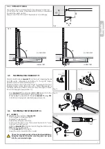
LEADER TI
LEADER TA
Leader 4 TA Leader 4 TA
24
Leader 4 TA
115
230V ~ 50Hz
1,2 - 1,7A
280W
8µF
150°C
2800 N
44
1400 rpm
110° deg
22”
300 Kg
2,75 m
40%
24V dc
0,5 - 0,75A
50W
__
__
2500 N
44
1600 rpm
110° deg
20”
200 Kg
2,5 m
80%
115V ~ 60Hz
2,0 - 2,3A
300W
30µF
150°C
3000 N
44
1700 rpm
110° deg
18”
200 Kg
2,75 m
40%
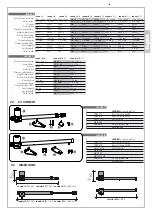
LEADER TI
1
2
3
4
5
1
2
3
4
5
Motor power supply
Max draw.
Power
Capacitor
Thermal protection
Adjustable thrust
Protection rating
Revolutions
Opening angle
Opening time (90°)
Leaf weight
Leaf length
Duty cycle
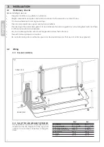
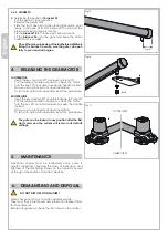
2.2 KIT CONTENT
Motor power supply
Max draw.
Power
Capacitor
Thermal protection
Adjustable thrust
Protection rating
Revolutions
Opening angle
Opening time (90°)
Leaf weight
Leaf length
Duty cycle
1
LEADER
Swing operator
2
SPIP0770
Rear RH bracket
T1
SPIP0870
Rear LH bracket
T1
3
MGR1410Z Fixing pack
MPE1226
4
SPIA0270
Front bracket
S3
5
Release key
1
LEADER
Swing operator
2
SPIP0770
Rear RH bracket
T1
SPIP0870
Rear LH bracket
T1
3
MGR1410Z Fixing pack
MPE1226
MRO12Z
MDAM12AB
4
SPIA0370
Front bracket
S4
5
Release key
2.3 DIMENSIONS
Содержание LEADER 3
Страница 1: ...01_17 LEADER Gearmotor for swing gates INSTALLATION MANUAL...
Страница 2: ......


