Page 15
Mounting the Motors (continued):
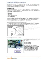
Affix the gate mounting bracket (S3) to the motor as
illustrated below. Slide the bracket into position on the
end of the motor arm and place the pivot pin (PR1) into
the locating hole. Fix firmly into position using the grub
screw (G1)
Mount the arm of the motor onto the gate. Ensure the
arm is perfectly straight and check the manual opening of
the leaf before definitively fixing the brackets to make sure
the gate can open fully to your required angle. Once
confirmed - bolt / weld the Gate Mounting bracket (S3)
securely into place. When the motor is secured on the
gate, engage the locking mechanism of the motor using
the release key and remove the release key.
Ensure the release keys for the motors are kept in a secure
place.
Motor Release Keys - IMPORTANT
Each motor is supplied with two release keys which are pre-cut for the locks barrel. There are only
two keys per barrel and are specific to the barrel. There is
NO
skeleton key for the motor. If keys are
lost, GateMotors will be unable to supply replacements and the lock barrel will need to be replaced.
Blank keys are available from GateMotors if extra copies of the keys are required.
Gate Stops
Once your closing and opening positions have been finalised, place your gate stops into position to
so the gate control board can regulate the opening and closing cycles (illustrated below):


