Page 16
Connecting the Motors to the Control Board
Once the motors are in place, we can look to connecting them to the control board. Each motor is
supplied and pre-fitted with 1.5M 4 core flex. The cables can be extended and circuit breakers can
be used in-between the motor and the control board.
Using extension cable
Some installations have a wider drive way than others and fused spurs are not always used. If an
extension cable is needed to connect to any of the motors, ensure you use 4 core 1.5mm Armoured
Cable. This cable arrangement should contain:
1 x Black Wire
1 x Brown Wire
1 x Blue / Grey Wire (neutral)
1 x Green/Yellow (earth)
Using the appropriate cable colour identification aids with correct connections. The cable should be
contained within a suitable flexible conduit when buried under the driveway. Armoured cable is
available from GateMotors and is available in 25M, 50M and 100M reels.
Using Fused Spur (interim circuit breaker) – Optional to Fit
The gate automation control board is equipped with fuses which govern the motors. This stops any
power surges reaching the motor and stops any current surge feedback to the control board.
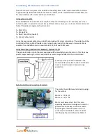
Fused spurs may be used in-between the
motor and its connection to the control board
to act as an extra means of power surge
protection.
Gate Control Board Connection Terminals
The control board features terminal groupings
for the motors.
Motor 1 = 13, 14, 15
Motor 2 = 16, 17, 18
Motor 1 will always start first. This is an
operating feature and is designed to cater for
gates where an overlay is used on a leaf to
keep the gates level. Whichever motor is
connected to terminals 13, 14 & 15 will be
identified by the control board as Motor 1.


