


Setup
Page 30 of 69
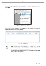
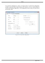
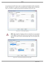
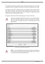
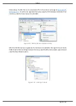
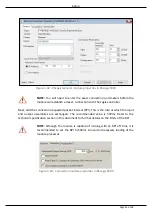
The two figures below show how DF1 messages are routed to the Logix tags using the DF1
Slave Map mode.
NOTE: It is your responsibility to ensure that the Logix tag array datatype and
size matches that of the DF1 File Number. Failing to do this can result in
communication faults.
Figure 3.22 - DF1 Slave mode configuration in the PLX50 Configuration Utility
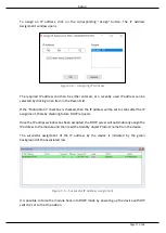
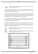
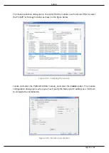
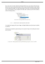
When receiving PLC2 messages, the Data File entered into the PLX50 Configuration Utility will
be “PLC2” because there are no Data Files in PLC2 message structures. Thus, the DF1 Node
address will be used to route the messages as shown below:
NOTE: It is your responsibility to ensure that the Logix tag array datatype and
size matches that of the PLC2 DF1 request. Failing to do this can result in
communication faults.
Figure 3.23 DF1 Slave mode config in the PLX50 Configuration Utility (PLC2 messages)
Содержание PLX51-DF1-MSG
Страница 1: ...PLX51 DF1 MSG DF1 Messenger DF1 to EtherNet IPTM Messenger December 2017 USER MANUAL...
Страница 4: ...Page 4 of 69...
Страница 10: ...Page 10 of 69...
Страница 48: ...Operation Page 48 of 69...
Страница 60: ...Page 60 of 69...
Страница 64: ...Page 64 of 69...
Страница 68: ...Page 68 of 69...