ProSoft Technology PLX51-DF1-MSG Скачать руководство пользователя страница 27

Setup 


Page 27 of 69 


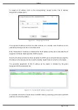
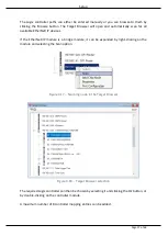
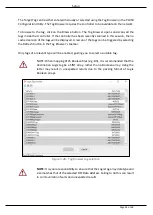
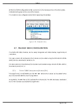
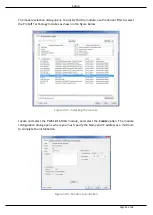
The  Logix  controller  paths  can  either  be  entered  manually  or  you  can  browse  to  them  by 
clicking  the  Browse  button.  The  Target  Browser  will  open  and  automatically  scan  for  all 
available EtherNet/IP devices. 
 
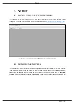
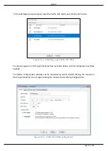
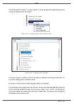
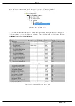
If  the  EtherNet/IP  module  is  a  bridge  module,  it  can  be  expanded  by  right-clicking  on  the 
module and selecting the Scan option. 


Figure 3.17. - Scanning node in the Target Browser 


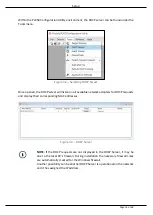
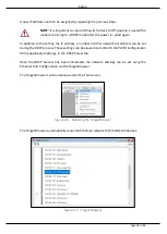
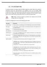
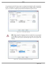
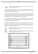
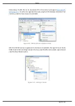
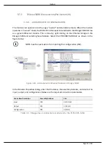
Figure 3.18. - Target Browser selection 

 
The required Logix controller can then be chosen by selecting it and clicking the Ok button, or 
by double-clicking on the controller module. 
 
A maximum number of 8 controller mapping entries can be added.  
 

Содержание PLX51-DF1-MSG

Страница 1: ...PLX51 DF1 MSG DF1 Messenger DF1 to EtherNet IPTM Messenger December 2017 USER MANUAL...

Страница 2: ...are 15 3 2 Network Parameters 15 3 3 Creating a New Project 20 3 4 DF1 parameters 22 3 5 Message Routing 26 3 5 1 DF1 Slave Mode 26 3 5 2 Scheduled Tag Mode 31 3 6 Module Download 35 3 7 RSLogix 5000...

Страница 3: ...nical Specifications 61 6 1 Dimensions 61 6 2 Electrical 62 6 3 Ethernet 62 6 4 DF1 63 6 5 Certifications 63 7 Support Service Warranty 65 7 1 Contacting Technical Support 65 7 2 Warranty Information...

Страница 4: ...Page 4 of 69...

Страница 5: ...diagnostics of the ProSoft Technology PLX51 DF1 MSG DF1 Messenger The PLX51 DF1 MSG provides intelligent data routing between EtherNet IP and DF1 which can help simplify the migration from PLC2 PLC3 P...

Страница 6: ...on Utility This program can be downloaded from www prosoft technology com free of charge The PLX50 Configuration Utility offers various configuration methods including a controller tag browser Hereaft...

Страница 7: ...ith the use of two PLX51 DF1 MSG s These can be configured in one of two modes either Simultaneous or Active Standby In the Simultaneous mode both modules route the same traffic to the same Logix cont...

Страница 8: ...ntral ControlLogix communicating to a number of remote DF1 devices e g MicroLogix and SLC stations may find the PLX51 DF1 MSG useful when upgrading to newer ControlLogix processors which no longer hav...

Страница 9: ...al PLX51 DF1 MSG Datasheet Example Code UDTs www prosoft technology com Ethernet wiring standard www cisco com c en us td docs video cds cde cde205_220_420 i nstallation guide cde205_220_420_hig Conne...

Страница 10: ...Page 10 of 69...

Страница 11: ...e and negative or ground voltage as well as the earth connection The RS232 port uses a four way connector This provides connection for the communication transmit TX receive RX and ground GND conductor...

Страница 12: ...s shown in the top view figure above DIP Switch Description DIP Switch 1 Used to force the module into Safe Mode When in Safe Mode the module will not load the application firmware and will wait for n...

Страница 13: ...ecification The DIN rail clip is mounted on the bottom of the module toward the back Use a flat screw driver to pull the clip downward This will enable you to mount the module onto the DIN rail Once t...

Страница 14: ...of the RS232 port is internally connected to the power connector earth Thus when using a shield it is important to connect the Earth terminal on the power connector to a clean earth Failing to do thi...

Страница 15: ...ogy com Figure 3 1 ProSoft PLX50 Configuration Utility Environment 3 2 NETWORK PARAMETERS The module has DHCP Dynamic Host Configuration Protocol enabled as factory default Thus a DHCP server must be...

Страница 16: ...ork adapters for DHCP requests and display their corresponding MAC addresses Figure 3 3 DHCP Server NOTE If the DHCP requests are not displayed in the DHCP Server it may be due to the local PC s firew...

Страница 17: ...ress will be set to static after the IP assignment thereby disabling future DHCP requests Once the IP address window has been accepted the DHCP server will automatically assign the IP address to the m...

Страница 18: ...rameters can be set during the DHCP process These settings can be viewed and edited in the PLX50 Configuration Utility Application Settings in the DHCP Server tab Once the DHCP process has been comple...

Страница 19: ...enu including the Port Configuration option Figure 3 8 Selecting Port Configuration The Ethernet port configuration parameters can be modified using the Port Configuration window Figure 3 9 Port Confi...

Страница 20: ...ty project must be created Under the File menu select New Figure 3 10 Creating a new project A PLX50 Configuration Utility project will be created showing the Project Explorer tree view To save the pr...

Страница 21: ...PLX51 DF1 MSG The device appears in the Project Explorer tree as shown below and its configuration window opened The device configuration window can be reopened by either double clicking the module i...

Страница 22: ...jor Revision The major revision of the PLX51 DF1 MSG ENIP Retry Limit The amount of EtherNet IP retries the module will make once no response was received from the Logix Controller ENIP TimeOut The ti...

Страница 23: ...configuration is shown in the figure below The DF1 general configuration window is opened by either double clicking on the module in the tree or right clicking the module and selecting Configuration F...

Страница 24: ...in Full Duplex mode Node Address The node address is dynamically changed to suite the required mapping Retry Limit The retry limit determines how many times the module must retry and message exchange...

Страница 25: ...below The DF1 Serial configuration window is opened by either double clicking on the module in the tree or right clicking the module and selecting Configuration In the configuration window select the...

Страница 26: ...G can operate completely independently from the Logix controller by directly reading and writing to Logix tags NOTE The DF1 Slave mode only works with PLC5 SLC Typed Read and Write messages as well as...

Страница 27: ...vices If the EtherNet IP module is a bridge module it can be expanded by right clicking on the module and selecting the Scan option Figure 3 17 Scanning node in the Target Browser Figure 3 18 Target B...

Страница 28: ...tively write to or read from a Logix tag using traditional File Numbers e g N7 F8 etc Figure 3 19 DF1 Slave Mapping NOTE When using PLC 2 messages there are no data files You are required to enter PLC...

Страница 29: ...File field as shown in figure 3 27 Below is an example of the target tag selection The Target Tag can be either entered manually or selected using the Tag Browser in the PLX50 Configuration Utility Th...

Страница 30: ...ion in the PLX50 Configuration Utility When receiving PLC2 messages the Data File entered into the PLX50 Configuration Utility will be PLC2 because there are no Data Files in PLC2 message structures T...

Страница 31: ...ration or programming required in either the DF1 device or the Logix controller Figure 3 24 Scheduled Tag configuration The Schedule Tag mode is configured in three steps First you must create a Targe...

Страница 32: ...chosen by selecting it and clicking the Ok button or by double clicking on the controller module A maximum number of 8 controller mapping entries can be added The second step is to configure the scan...

Страница 33: ...and message size The Device Type field specifies the type of message that will be sent to the DF1 device There are two options PLC5 and SLC The latter should be selected when using a MicroLogix device...

Страница 34: ...tags can be triggered by selecting the Refresh button in the Tag Browser s toolbar Only tags of a relevant type will be enabled guiding you to select a suitable tag NOTE When mapping PLC5 Boolean fil...

Страница 35: ...default to the IP address of the module as set in the module configuration It can be modified if the PLX51 DF1 MSG is not on a local network The Connection path can be set by right clicking on the mo...

Страница 36: ...notified that the download was successful Figure 3 32 Successful download During the download process the module s time will be compared to that of the PC s time Should the difference be greater than...

Страница 37: ...ontrollers For Logix versions 20 and beyond the modules can be added using the EDS Add On Profile AOP which is described in section 3 7 1 For older versions 19 and below the module must be added using...

Страница 38: ...EDS Hardware Installation Tool shortcut under the Tools menu in Studio 5000 Figure 3 35 EDS Hardware Installation Utility After the EDS file has been registered the module can be added to the Logix I...

Страница 39: ...oSoft Technology modules as shown in the figure below Figure 3 37 Selecting the module Locate and select the PLX51 DF1 MSG module and select the Create option The module configuration dialog opens whe...

Страница 40: ...O tree Figure 3 39 Logix IO tree The Module Defined Data Types are automatically created during the instantiation process These data types provide meaningful structures to the module data An excerpt o...

Страница 41: ...e RSLogix 5000 and selecting New Module Select the ETHERNET MODULE as shown in the figure below NOTE See the next section for importing the configuration L5X Figure 3 41 Add a Generic Ethernet Module...

Страница 42: ...ted packet interval RPI This is the rate at which the input and output assemblies are exchanged The recommended value is 500ms Refer to the technical specification section in this document for further...

Страница 43: ...Data Type The assemblies are then assigned to the UDTs with a ladder copy instruction COP as shown in the figure below Figure 3 44 RSLogix 5000 I O module tree 3 7 2 2 IMPORTING UDTS AND MAPPING ROUTI...

Страница 44: ...es Two controller tags representing the Input and Output assemblies A routine mapping the PLX51 DF1 MSG module to the aforementioned tags To change the routine to map to the correct PLX51 DF1 ENI modu...

Страница 45: ...he diagnostics section for a more detailed explanation 4 2 RSLOGIX 5000 ASSEMBLIES When the module operates in a Logix owned mode the Logix controller establishs a class 1 cyclic communication connect...

Страница 46: ...module is currently routing DeviceTemperature REAL The internal temperature of the module DF1RxPacketCount DINT The total number of DF1 packets received by the module DF1TxPacketCount DINT The number...

Страница 47: ...rameter Datatype Description RoutingInhibit BOOL This bit inhibits the module s routing capabilities When set no DF1 messages are routed This may be required in applications running a redundant DF1 ne...

Страница 48: ...Operation Page 48 of 69...

Страница 49: ...are has been corrupted or there is a hardware fault the module will have a red Module LED If the LED is green then the module has booted and is running correctly Activity The Activity LED is used for...

Страница 50: ...full by the PLX50 Configuration Utility or using the web server in the module To view the module s status in the ProSoft PLX50 Configuration Utility the module must be online Right click on the modul...

Страница 51: ...nhibited in the output assembly of the module Transaction Rate The number of DF1 messages per second that the module is currently routing Up Time Indicates the elapsed time since the module was powere...

Страница 52: ...s received by the module STX count The number of DF1 STX Start of Text delimiters received by the module SOH count The number of DF1 SOH Start of Header delimiters received by the module NAK count The...

Страница 53: ...tag not existing Privilege Violation Errors The number of tag read and tag write transactions that failed due to a privilege violation error This may be caused by the External Access property of the...

Страница 54: ...Diagnostics Page 54 of 69 The fields in the Map Items tab adjust to suite the appropriate mode Figure 5 6 Map Item status...

Страница 55: ...Packet Capture item in the Project Explorer tree Figure 5 7 Selecting DF1 Packet Capture The DF1 Packet Capture window opens and automatically starts capturing all DF1 packets NOTE The module keeps a...

Страница 56: ...packet Received packets are checked for valid DF1 constructs and valid checksums Dirn The direction of the packet either transmitted Tx or received Rx Src DF1 node address of the message source Dest...

Страница 57: ...ved to a file for further analysis by selecting the Save button on the toolbar Previously saved DF1 Packet Capture files can be viewed by selecting the DF1 Packet Capture Viewer option in the tools me...

Страница 58: ...nt Viewer option in the Project Explorer tree Figure 5 11 Selecting the module Event Log The Event Log window opens and automatically reads all the events from the module The log entries are sorted to...

Страница 59: ...tion Utility or RSLogix 5000 to view various diagnostics of the module This includes Ethernet parameters system event log advanced diagnostics and application diagnostics DF1 diagnostics NOTE The web...

Страница 60: ...Page 60 of 69...

Страница 61: ...9 6 TECHNICAL SPECIFICATIONS 6 1 DIMENSIONS Below are the enclosure dimensions as well as the required DIN rail dimensions All dimensions are in millimetres Figure 6 1 PLX51 DF1 MSG enclosure dimensio...

Страница 62: ...n Yes terminal based Emissions IEC61000 6 4 ESD Immunity EN 61000 4 2 Radiated RF Immunity IEC 61000 4 3 EFT B Immunity EFT IEC 61000 4 4 Surge Immunity Surge IEC 61000 4 5 Conducted RF Immunity IEC 6...

Страница 63: ...ped Read PLC 5 Typed Write SLC Typed Read SLC Typed Write PLC 2 Unprotected Read PLC 2 Unprotected Write PLC 2 Unprotected Bit Write Scheduled Tag Mode Message Support PLC 5 Typed Read PLC 5 Typed Wri...

Страница 64: ...Page 64 of 69...

Страница 65: ...If the issue is hardware related we will also need information regarding 1 Module configuration and associated ladder files if any 2 Module operation and any unusual behavior 3 Configuration Debug sta...

Страница 66: ...n English Chinese Japanese Korea Phone 603 7724 2080 korea prosoft technology com Languages spoken English Korean Regional Office Phone 33 0 5 34 36 87 20 europe prosoft technology com Languages spoke...

Страница 67: ...hnology com Andean Countries Central America Caribbean Phone 507 6427 48 38 andean prosoft technology com Languages spoken Spanish English Southern Cone Argentina Bolivia Chile Paraguay Uruguay Phone...

Страница 68: ...Page 68 of 69...

Страница 69: ...ctor 14 EtherNet IP 5 9 F File Number 26 28 30 31 33 34 firmware upgrade 22 G ground GND 11 I input assembly 46 51 input voltage 14 L LED 49 Logix tag 22 26 28 30 31 33 34 45 46 Logix Tag Map 26 30 O...

Отзывы: