


Installation
Page 12 of 69
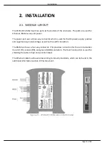
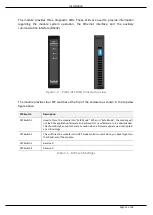
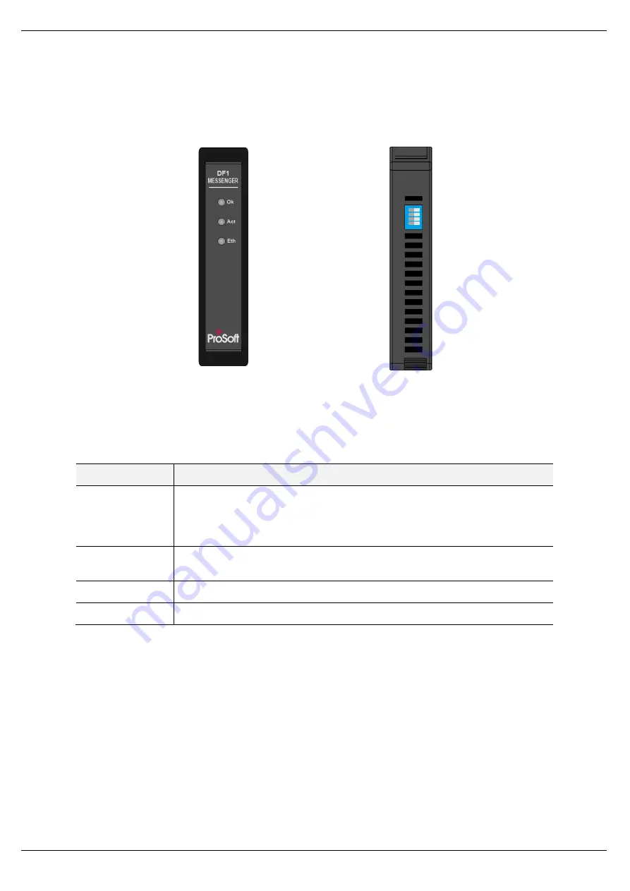
The module provides three diagnostic LEDs. These LEDs are used to provide information
regarding the module system operation, the Ethernet interface, and the auxiliary
communication interface (RS232).
Figure 2.2. – PLX51-DF1-MSG front and top view
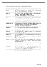
The module provides four DIP switches at the top of the enclosure as shown in the top view
figure above.
DIP Switch
Description
DIP Switch 1
Used to force the module into “Safe Mode”. When in “Safe Mode”, the module will
not load the application firmware and will wait for new firmware to be downloaded.
This should only be used in the rare occasion when a firmware update was interrupted
at a critical stage.
DIP Switch 2
This will force the module into DHCP mode which is useful when you have forgotten
the IP address of the module.
DIP Switch 3
Reserved
DIP Switch 4
Reserved
Table 2.1. - DIP Switch Settings
Содержание PLX51-DF1-MSG
Страница 1: ...PLX51 DF1 MSG DF1 Messenger DF1 to EtherNet IPTM Messenger December 2017 USER MANUAL...
Страница 4: ...Page 4 of 69...
Страница 10: ...Page 10 of 69...
Страница 48: ...Operation Page 48 of 69...
Страница 60: ...Page 60 of 69...
Страница 64: ...Page 64 of 69...
Страница 68: ...Page 68 of 69...