background image

REHATEAM s.r.l.—vicolo Negrelli 

5

31040 

Castagnole di Paese TV  

-

 www.rehateamprogeo.com


Service Manual CARBOMAX    16


SERVICE MANUAL 

FOOTPLATE DISTANCE 

Sliding system (until 2018) 

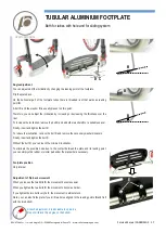
Adjustment with sliding system.  

Loosen the bolt 

A

 of the clamp on both sides. 

With a rubber or plastic mallet, gently hit on the upper or lower points that are indicated by the black arrows according to the adjustment you 
need to carry out. 

Once you reach the desired height, tighten the bolt 

A

 on one side. 

Check the wide side of the footrest plate is parallel to the ground. 

If necessary, raise or lower the tube on the side that is not fixed yet. Finally, tighten the bolt 

A

 of the second side.  

After each adjustment, check that: 

Between the lower side of the footplate and the ground, there is at least a 2 cm gap. 

There is no interference between footplate and casters. 

The height adjustment of the footplate can affect the directionality of the wheelchair, in fact, if the footplate is slightly tilted on either side, the 
wheelchair will go right or left. In such case, correct the height of the right or left tube. 

Содержание CARBOMAX

Страница 1: ...REHATEAM s r l vicolo Negrelli 5 31040 Castagnole di Paese TV www rehateamprogeo com Service Manual CARBOMAX 1 S E R V I C E M A N U A L CARBOMAX Rev 0 06 05 2020 SERVICE MANUAL ENGLISH...

Страница 2: ...any non standard requirements or modifications to allow them to evaluate such modifications and verify that they will not compromise the normal and safe use of the wheelchair Any modification of the...

Страница 3: ...system 06 FORK ANGLE 07 DIRECTIONALITY 09 REAR HEIGHT 10 SETTING point of balance 11 CAMBER AND CONVERGENCY 13 BRAKE 14 BRAKE SPACING 15 FOOTPLATE DISTANCE tubes with holes 16 FOOTPLATE DISTANCE slid...

Страница 4: ...fork s sizes Screw off the bolt V while holding the other Remove the axle P Position the caster to another hole insert the axle and fix the bolt V holding the one on the other side Pay attention to th...

Страница 5: ...on the bolts V A Work on a flat and even surface Loosen the two bolts A Slide the support upward or downward to the desired height Tighten the two bolts A Repeat the same operations on the other side...

Страница 6: ...e fork s axle proceed as above mentioned until reaching the correct angle You can also measure the perpendicularity by turning the fork by 360 during the full turn the wheel has to touch the surface i...

Страница 7: ...t turn smoothly Clean or change the bearings FRONT WHEELS The casters are not adjusted at the same height Adjust the front wheels at the same height The tyres of the two front wheels are different or...

Страница 8: ...axle tilts by 1 right or left according to how to cast them in the hollows see images Note you can cast the inserts only as indicated in these images Once you have casted the inserts C0 or C2 it is a...

Страница 9: ...When tightening this bolt check that the inner plate of the clamp does not turn you can hold it with your fingers in fact if it turns the clamp will not take hold of the frame properly Finally tighten...

Страница 10: ...ide first Then measure the distance X between the rear side of the rear support and the backrest plate Adjust and fix the other side respecting the same distance When tightening each bolt check that t...

Страница 11: ...ssario regolare la campanatura Follows next page WORK ON A FLAT AND EVEN SURFACE The wheel receiver gives the rear wheel camber cambered receiver The two wheel receivers are fixed to the rear axle thu...

Страница 12: ...a reamer to remove any possible tiny deformation see also adjustment sheet quick release axle It may be a little harder to position and fix the other side due to the pressure given by the seat canvas...

Страница 13: ...justment A good adjustment has the brake not too hard to engage but braking so you will have to find the suitable compromise Once reached the correct position tighten the headless bolt A Carry out the...

Страница 14: ...vice and heat it with a hot air blower because the bolt is locked with strong lock thread glue DO NOT FORCE WHEN UNSCREWING IT you may damage the bolt s head irremediably Once you have removed the bo...

Страница 15: ...of the support C The footplate tube s holes and the hole of the support B must be aligned Finally tighten the bolt A on both sides of the frame Do not force screwing the bolt you may damage the threa...

Страница 16: ...ght tighten the bolt A on one side Check the wide side of the footrest plate is parallel to the ground If necessary raise or lower the tube on the side that is not fixed yet Finally tighten the bolt A...

Страница 17: ...a suitable spacer Finally insert and tighten the bolt C To reduce the inclination remove the bolt C and remove the necessary washers spacers Finally insert and tighten the bolt C Without the bolt C yo...

Страница 18: ...y to cut the lower side of the If the maximum height you can reach is not enough it is necessary to change the tube Warning to guarantee a good stability between the fixing hole and the lower side of...

Страница 19: ...tube in fact the hole 1 will be underneath and within the tube of the backrest structure While drilling the hole on the tube pay attention to aligning the handle grip if present Should you cut off th...

Страница 20: ...hten the bolts Now check the locking system If the locking pin D does not lock or there is too much play it is necessary to adjust the end run bolt B Loose the nut C fold the backrest and screw or uns...

Страница 21: ...gently hit a little harder if necessary the hub or spokes of the wheel and try to remove it Loosen the grab screw A and try to remove the wheel Loosen the two bolts B and the bolt nut C and try to rem...

Отзывы: