
Usage instructions SPEEDY F4 & F2
32
alignment of the caster-wheel bearing blocks is
precisely aligned to the tyre size ordered and
the welded caster-wheel bearing blocks cannot
subsequently be adjusted.
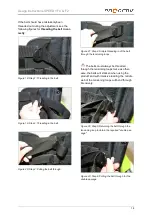
Figure 80: Angle-adjustable caster wheel bearing
block
Recommended equipment:
The spoke guard prevents hands and fingers
entering and being trapped in the wheels when
riding. The risk of injury is thus minimised.
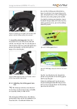
Figure 81: Spoke guard for minimising the risk of
hands and fingers getting trapped
22 Caster wheels
22.1 Replacing the caster wheels
The following instructions are intended
for and may only be carried out by a rehabilita-
tion specialist dealer or PRO ACTIV
The caster wheels of the product are, depend-
ing on the type of casters, either fastened with
two M6 axle fixing screws or one M6 axle fixing
screw and a M6 nut.
22.1.1 Replacing the caster wheels when
mounted using two axle fixing
screws
To
remove a caster wheel
, unscrew the M6
axle fixing screws (AF 4 mm) on one side.
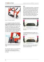
Figure 82: M6 axle fixing screw of caster wheel axle
(view from outer side of product)
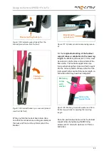
Figure 83: Caster wheel with aluminium hexagon
socket
Now you can see the aluminium axle with a
hexagon socket (AF 4 mm) in the middle of the
axle. This hexagon socket is used to fix the
axle in place, while the second M6 axle fixing
screw (AF 4 mm) is unscrewed. To do this,
insert an Allen key (AF 4 mm) into the hexagon
socket on the aluminium axle and hold it still.
At the same time, unscrew the remaining M6
axle fixing screw (AF 4 mm) on the other side.
Now the caster wheel can be removed from
the fork. One spacer each is mounted to the
right and left on the caster wheel that you are
Aluminium axle with
hexagon socket
M6 axle fixing screws
Angle-adjustable
caster wheel bearing block









![Dietz AS[01] Operating Instructions Manual preview](http://thumbs.mh-extra.com/thumbs/dietz/as-01/as-01_operating-instructions-manual_2495921-01.webp)


