Usage instructions SPEEDY F4 & F2
48
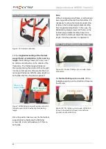
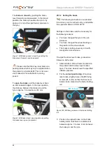
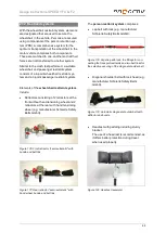
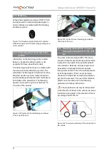
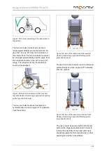
Figure 134: Central anti-tipping support removed
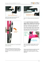
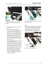
Figure 135: Fixing shells on the rear frame cross
section
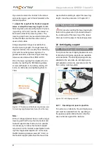
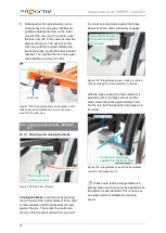
Figure 136: Centring half shells on the front frame
cross bar
24.3 Safety instructions
The anti-tipping support is designed ex-
clusively to minimise the risk of tipping over
backwards. It is not suitable for reducing the
risk of tipping forwards or to the side. There is
no safety equipment on offer for minimizing
these risks. For this reason, handling these
risks need to be learnt in cooperation with your
therapists and doctors.
Before using the product, each time after
loading the anti-tipping supports and after eve-
ry adjustment to the product, make sure that
the anti-tipping supports are fully functional. In
this case, it must not be possible to swivel the
anti-tipping supports to the side when in oper-
ating position without having to unlock them
first.
The lower edge of the anti-tipping wheels
may not be more than 5
cm from the ground. If
a larger gap is required or necessary, then you
need to work with your therapists and doctors
to practice and learn to handle the increased
risk of tipping.
If the functionality of the anti-tipping sup-
ports is no longer ensured or if you are in any
doubt about their flawless function, have them
checked by your rehabilitation specialist dealer
and repaired before any further use. Otherwise
there is an increased risk or falling of getting
injured.
25 Brakes
25.1 Knee lever brake
25.1.1 Opening and closing the brake
The knee lever brake can be equipped with
different brake levers, such as, e.g. standard
brake lever, long brake lever, flared brake lever
and flip-down brake handle. The brake lever
can be mounted in the standard position, or
low. However, operation is identical for all of
these brake levers.
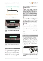
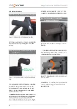
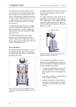
Figure 137: Knee lever brake system with standard
brake lever
Centring half shells
Fixing shells
Clamping bracket with clamp levers
and fixing hooks
Fixing hooks of the anti-tipping support


