Usage instructions SPEEDY F4 & F2
56
Settings on the brake could be necessary for
the following reasons:
You have changed the tyre or the tyre
pressure.
You have changed the wheel tracking or
the position of the drive wheels.
The brake is pulling unevenly or insuffi-
ciently after extended use.
To adjust the integrated brake, proceed as
follows on both sides:
1. Initial situation: Drive wheels mounted on
the product and the integral brakes open.
The drive wheels have the specified infla-
tion pressure.
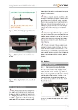
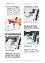
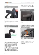
2. Undo the M5 clamp screws (AF 4 mm)
slightly so that the integral brake can be
pushed in the welded-on bracket with the
splined shaft.
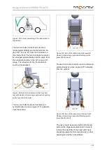
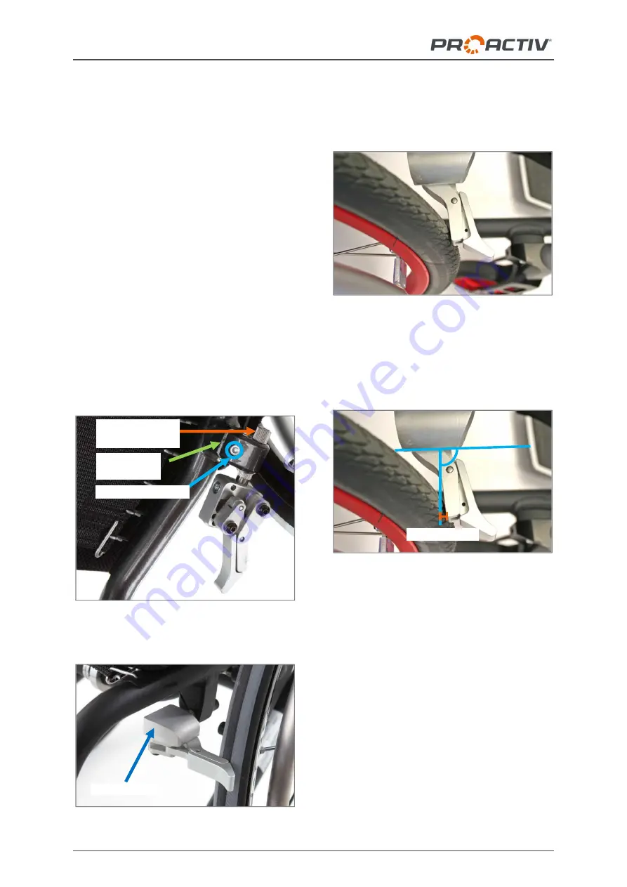
Figure 164: Description overview of the integrated
brake (product view from below)
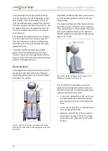
Figure 165: Brake mount
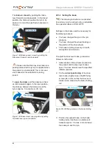
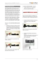
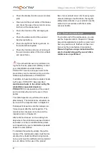
3. Press the front part of the control element
to the right or left outwards until the brake
element rests against the tyre. Do not
close the brake completely.
Figure 166: Brake element resting on the tyre
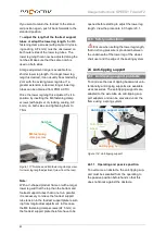
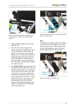
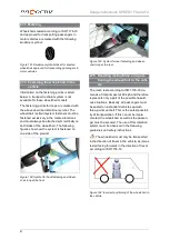
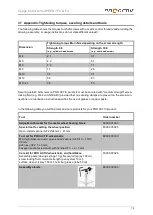
4. Slide the integral brake with the splined
shaft in the welded-on bracket so that the
braking element is positioned as shown in
the following figure:
Figure 167: Brake element after correct positioning
of the integral brake
5. Tighten up the M5 clamp screw (AF 4 mm)
again to 4 Nm.
6. Then check the correct setting of the
brakes: On a slope (7° gradient) the prod-
uct should stand firm with the brake ap-
plied. This will happen if, with the brake
closed, the tyre is depressed or deformed
by approximately 4 mm by the brake ele-
ment (at prescribed air pressure in the
tyres).
•
approx. 4 mm
Brake mount
M5 clamp screws
Welded-on
bracket
Integral splined
shaft


