Usage instructions SPEEDY F4 and F2
31
both sides by moving the wheelbase extension
slightly downwards and pull it away from the
product to the rear.
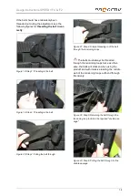
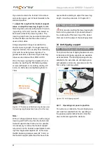
Figure 76: Quick Pin locking knob
Hint:
The Quick Pins can then be inserted in the
holes of the wheelbase extension to prevent
them being lost (Fig. 72) .
For
changing the drive wheels
between the
wheelchair axle and the axle of the wheelbase
extension, proceed as described Chapter 21.1.
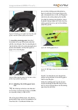
Figure 77: Wheelchair axle and wheelbase exten-
sion axle (view from outer side of product without
drive wheel)
Adjusting the angle of the "Removable
wheelbase extension with adjustable angle"
The "Removable wheelbase extension with
adjustable angle" allows the position of the
wheelbase extension axle, and thus the seat
height, to be adjusted. The seat height is ad-
justable in 6°-steps via a Hirth-type joint.
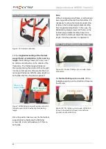
To adjust the angle, loosen the two M6 fixing
screws (AF 5 mm) and the M8 fixing screw (AF
6 mm) Now you can adjust the angle via the
Hirth-type joint. Then tighten the M6 fixing
screws (AF 5 mm) to 10 Nm and the M8 fixing
screw (AF 6 mm) to 20 Nm.
Figure 78: M8 and M6 fixing screws for adjusting the
angle of the "Removable wheelbase extension with
adjustable angle"
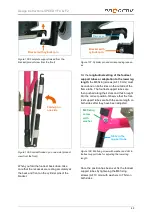
Figure 79: Examples of angle adjustments for the
wheelbase extension
21.6 Other
If tyres, inner tubes or handrims need to be
replaced, please contact your rehabilitation
specialist retailer.
Please note that changing one type of tyres to
another size is only possible with versions with
adjustable caster-wheel bearing blocks (cannot
be retrofitted), as with welded caster-wheel
bearing blocks the frame design including the
Locking knob
Axle of the wheelbase extension
Wheelchair axle
M8 fixing screw
M6 fixing screws


