Installation and Wiring
56
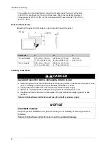
Panel Cut Dimensions
Based on the panel cut dimensions, open a mount hole on the panel.
Installing to the Panel
You can attach a commercial-type arm or wall-mount adapter using the arm mounting holes
(VESA 75 mm specification) at the back of this product. Attach the four (4) M4 attachment
screws (screw length: 10 mm [0.4 in]). The torque required for these screws is 0.7 to 0.8 N•m
(6.2 to 7.1 lb-in).
Display size
A
B
C
12.1-inch models
301.5 mm (+1/-0 mm)
(11.87 in [+0.04/-0 in])
227.5 mm (+1/-0 mm)
(8.96 in [+0.04/-0 in])
1.6...5 mm
(0.06...0.2 in)
15-inch models
383.5 mm (+1/-0 mm)
(15.1 in [+0.04/-0 in])
282.5 mm (+1/-0 mm)
(11.12 in [+0.04/-0 in])
DANGER
HAZARD OF ELECTRIC SHOCK, EXPLOSION, OR ARC FLASH
Remove all power from the device before removing any covers or elements of the system, and
prior to installing or removing any accessories, hardware, or cables.
Unplug the power cable from both this product and the power supply.
Always use a properly rated voltage sensing device to confirm power is off.
Replace and secure all covers or elements of the system before applying power to this
product.
Failure to follow these instructions will result in death or serious injury.
NOTICE
EQUIPMENT DAMAGE
Keep this product stabilized in the panel-cut while you are installing or removing the screw
fasteners.
Failure to follow these instructions can result in equipment damage.
Содержание FP5000 Series
Страница 1: ...FP5000 Series User Manual FP5000 MM01 EN PDF_02...
Страница 6: ...6...
Страница 10: ...10...
Страница 22: ...Overview 22 KC Markings...
Страница 26: ...Device Connectivity 26...
Страница 30: ...Parts Identification and Functions 30...
Страница 48: ...Dimensions 48 FP 5600TPD External Dimensions 1 Front 2 Left 3 Bottom...
Страница 50: ...Dimensions 50 FP 5700TPD External Dimensions 1 Front 2 Left 3 Bottom...
Страница 52: ...Dimensions 52...
Страница 72: ...Installation and Wiring 72...
Страница 88: ...System Specifications and Launcher 88...


