


Installation and Wiring
54
Installation
Section 6.1
Installation
Installation Procedures
Introduction
This product is designed for use on a flat surface of Type 1, Type 4X (Indoor Use Only) or Type 13
Enclosure.
Mount this product in an enclosure that provides a clean, dry, robust and controlled environment
(IP65F
*1
, IP66F
*1
, IP67F
*1
, Type 1, Type 4X [Indoor Use Only], or Type 13 Enclosure).
When using a factory-installed front USB cover (without screw), the front surface is IP65F
*1
,
IP67F
*1
or Type 1 Enclosure. When using a front USB cover (with screw
*2
) by Pro-face (Model
Number PFXZCDCVUS1), the front surface is IP66F
*1
, IP67F
*1
, Type 1, Type 4X (Indoor Use
Only) or Type 13 Enclosure.
Regardless of using a factory-installed front USB cover or a front USB cover with screw, when the
cover is open, the front surface is Type 1 Enclosure.
Be aware of the following when building this product into an end-use product:
The rear face of this product is not approved as an enclosure. When building this product into
an end-use product, be sure to use an enclosure that satisfies standards as the end-use
product’s overall enclosure.
This product must be used indoors only.
Install and operate this product with its front panel facing outward.
*1 IP65F, IP66F and IP67F are not part of the UL certification.
*2 The necessary torque is 0.5 N•m (4.4 lb-in).
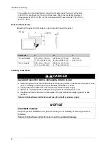
Installation Requirements
Display front surface
Enclosure front surface
Without screw
With screw
IP65F, IP67F, Type 1
IP66F, IP67F, Type 1, Type 4X
(Indoor Use Only), Type 13
IP65F, IP66F, IP67F, Type 1,
Type 4X (Indoor Use Only),
Type 13
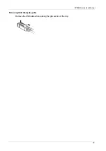
Check that the installation wall or cabinet surface is flat, in good condition and has no jagged
edges. Metal reinforcing strips may be attached to the inside of the wall, near the panel-cut,
to increase its rigidity.
Decide on the thickness of the enclosure wall, based on the level of strength required:
1.6...5 mm (0.06...0.2 in).
Even if the installation wall thickness is within the recommended range for the panel cut
dimensions, depending on wall’s material, size, and installation location of this product and
other devices, the installation wall could warp. To prevent warping, the installation surface
may need to be strengthened.
Содержание FP5000 Series
Страница 1: ...FP5000 Series User Manual FP5000 MM01 EN PDF_02...
Страница 6: ...6...
Страница 10: ...10...
Страница 22: ...Overview 22 KC Markings...
Страница 26: ...Device Connectivity 26...
Страница 30: ...Parts Identification and Functions 30...
Страница 48: ...Dimensions 48 FP 5600TPD External Dimensions 1 Front 2 Left 3 Bottom...
Страница 50: ...Dimensions 50 FP 5700TPD External Dimensions 1 Front 2 Left 3 Bottom...
Страница 52: ...Dimensions 52...
Страница 72: ...Installation and Wiring 72...
Страница 88: ...System Specifications and Launcher 88...