background image

FP5000 Series User Manual


21

European (CE) Compliance

CE Compliance Note

The product described in this manual comply with the European Directives concerning 
Electromagnetic Compatibility and Low Voltage (CE marking) when used as specified in the 
relevant documentation, in application for which they are specifically intended, and in connection 
with approved third-party products. 

Содержание FP5000 Series

Страница 1: ...FP5000 Series User Manual FP5000 MM01 EN PDF_02...

Страница 2: ...ncommercial use all or part of this document on any medium whatsoever without permission of Schneider Electric given in writing You also agree not to establish any hypertext links to this document or...

Страница 3: ...ntification and Functions 27 FP 5600TPD 5700TPD 28 LED Indications 29 Chapter 4 Specifications 31 4 1 General Specifications 32 Electrical Specifications 33 Environmental Specifications 34 Structural...

Страница 4: ...ivers Utilities 75 Settings Workflow 76 Installing the Drivers 77 Installing the Utilities 79 7 2 Launcher 80 About the Launcher 81 Display Settings 83 PC Settings 87 Chapter 8 Maintenance 89 Regular...

Страница 5: ...hazards or to call attention to information that clarifies or simplifies a procedure PLEASE NOTE Electrical equipment should be installed operated serviced and maintained only by qualified personnel...

Страница 6: ...6...

Страница 7: ...ownload the manuals related to this product such as the software manual from our support site at http www pro face com trans en manual 1001 html Product Related Information Critical alarm indicators a...

Страница 8: ...e during and after a path failure Examples of critical control functions are emergency stop and overtravel stop power outage and restart Separate or redundant control paths must be provided for critic...

Страница 9: ...ED EQUIPMENT OPERATION Do not use this product as the only means of control for critical system functions such as motor start stop or power control Do not use this equipment as the only notification d...

Страница 10: ...10...

Страница 11: ...package contents and standards What Is in This Chapter This chapter contains the following topics Topic Page Model Number Configuration 12 Model Numbers 13 Package Contents 14 Revision 15 Certificati...

Страница 12: ...figuration The following describes the configuration of model numbers Digit position 1 2 3 4 5 6 7 8 9 10 11 12 P F X model series size type LCD touch panel power supply FP 5 6 12 1 inch 7 15 inch 00...

Страница 13: ...as a universal model number For more information on product models and their matching global codes please refer to the following URL http www pro face com trans en manual 1003 html Series Display size...

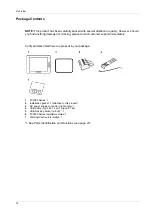
Страница 14: ...support immediately Verify all items listed here are present in your package 1 FP5000 Series 1 2 Installation gasket 1 attached to this product 3 DC power supply connector right angle 1 4 USB clamp Ty...

Страница 15: ...FP5000 Series User Manual 15 Revision You can identify the product version PV revision level RL and the software version SV from the product label...

Страница 16: ...UL 508 and CSA C22 2 No 142 Industrial Control Equipment Underwriters Laboratories Inc ANSI ISA 12 12 01 and CSA C22 2 No213 Electrical Equipment for Use in Class I Division 2 Hazardous Classified Loc...

Страница 17: ...se in factory systems When using this product in a system the system should comply with the following standards in regards to the installation environment and handling WEEE Directive 2012 19 EU RoHS D...

Страница 18: ...lectromagnetic energy to cause interference in nearby devices Install and test this product to ensure that the electromagnetic energy generated by nearby devices does not interfere with the operation...

Страница 19: ...wn to be non hazardous Always confirm that this product is suitable for use in hazardous locations by checking the ANSI ISA 12 12 01 or CSA C22 2 N 213 certification appears on the product labeling Do...

Страница 20: ...rated voltage sensing device to confirm power is off Replace and secure all covers or elements of the system before applying power to this product Use only the specified voltage when operating this pr...

Страница 21: ...ribed in this manual comply with the European Directives concerning Electromagnetic Compatibility and Low Voltage CE marking when used as specified in the relevant documentation in application for whi...

Страница 22: ...Overview 22 KC Markings...

Страница 23: ...tivity iDisplay_PF 12 2017 Device Connectivity Chapter 2 Device Connectivity Introduction This chapter presents the equipment you can connect to this product What Is in This Chapter This chapter conta...

Страница 24: ...the front USB Type A interface 6 You can use Pro face products Refer to our website http www pro face com NOTE When you connect more than one display to the host in the following combinations a touch...

Страница 25: ...DOP121 Environmental resistant cover for the display 1 piece 15 inch Environment Cover PFXZCDOP151 Enhanced Front USB Cover With Screw PFXZCDCVUS1 Front USB cover with fixing screw corresponding to IP...

Страница 26: ...Device Connectivity 26...

Страница 27: ...s iDisplay_PF 12 2017 Parts Identification and Functions Chapter 3 Parts Identification and Functions Introduction This chapter presents the part locations and functions What Is in This Chapter This c...

Страница 28: ...ls the brightness of the backlight B Front USB cover USB Type A interface is located behind the front USB cover C Front USB Type A interface Conforms to USB 2 0 Type A x 1 D USB masking sticker mini B...

Страница 29: ...ht is burned out When the screen does not display always check the LED status and do not perform touch operations Color Indicator Description Green ON In operation LED fade Backlight is OFF Standby Mo...

Страница 30: ...Parts Identification and Functions 30...

Страница 31: ...17 Specifications Chapter 4 Specifications Introduction This chapter presents the product specifications What Is in This Chapter This chapter contains the following sections Section Topic Page 4 1 Gen...

Страница 32: ...ral Specifications Section 4 1 General Specifications What Is in This Section This section contains the following topics Topic Page Electrical Specifications 33 Environmental Specifications 34 Structu...

Страница 33: ...ower is supplied to external devices 17 W or less 21 W or less Backlight ON 100 Power is not supplied to external devices 14 W or less 18 W or less Backlight adjusted 20 Power is not supplied to exter...

Страница 34: ...ess non conductive levels Pollution degree For use in Pollution Degree 2 environment Corrosive gases Free of corrosive gases Atmospheric pressure operating altitude 800 1 114 hPa 2 000 m 6 561 ft or l...

Страница 35: ...be sure to replace the installation gasket regularly 2 For dimensional tolerance everything 1 0 mm 0 04 0 in and R in angle are below R3 R0 12 in 3 Even if the installation wall thickness is within t...

Страница 36: ...NT DAMAGE Do not expose the device to direct sunlight Failure to follow these instructions can result in injury or equipment damage NOTICE STORAGE AND OPERATION OUTSIDE OF SPECIFICATIONS Store the pan...

Страница 37: ...Series User Manual 37 Functional Specifications Section 4 2 Functional Specifications What Is in This Section This section contains the following topics Topic Page Display Specifications 38 Touch Pan...

Страница 38: ...45 76 x H184 32 mm W9 68 x H7 26 in W304 1 x H228 1 mm W11 97 x H8 98 in Display colors 16 million colors Backlight White LED Not user replaceable When replacement is required contact your local distr...

Страница 39: ...FP5000 Series User Manual 39 Touch Panel Touch panel type Resistive film analog multi touch Touch panel resolution 1 024 x 1 024 Touch panel service life 1 million times or more...

Страница 40: ...Interface Specifications Section 4 3 Interface Specifications What Is in This Section This section contains the following topics Topic Page Interface Specifications 41 Interface Connection 42 DVI D I...

Страница 41: ...Power supply voltage 5 Vdc 5 Maximum supply current 500 mA Maximum transmission distance 5 m 16 4 ft USB Type B interface Connector USB 2 0 Type B x 1 Maximum transmission distance 5 m 16 4 ft Video...

Страница 42: ...ld wiring apparatus keyboards mouse are permitted for use on the front USB port Type A of associated field wiring non incendive apparatus this product In addition to being non incendive any equipment...

Страница 43: ...Front USB Type A Open circuit voltage Voc 5 25 V Short circuit current Isc 1300 mA Associated capacitance Ca 265 F Associated inductance La 16 H Circuit parameters Front USB mini B Maximum input volt...

Страница 44: ...vision 2 wiring methods Associated non incendive field wiring apparatus Non incendive field wiring apparatus Voc Vmax Isc Imax Ca Ci Ccable La Li Lcable DANGER POTENTIAL FOR EXPLOSION Verify the power...

Страница 45: ...uce the risk of damaging the circuit Failure to follow these instructions will result in death or serious injury Product side Pin No Signal name Direction 1 TMDS DATA 2 Input 2 TMDS DATA 2 Input 3 TMD...

Страница 46: ...eration use the recommended DVI D cable When you use a commercial type cable the maximum length is 5 m Display Resolution Resolution H sync kHz V sync Hz Dot clock MHz 640 x 480 31 469 59 940 25 175 8...

Страница 47: ...er Manual Dimensions iDisplay_PF 12 2017 Dimensions Chapter 5 Dimensions Introduction This chapter presents the product external dimensions What Is in This Chapter This chapter contains the following...

Страница 48: ...Dimensions 48 FP 5600TPD External Dimensions 1 Front 2 Left 3 Bottom...

Страница 49: ...center of installation fastener screws 1 Right 2 Rear 3 Left 4 Bottom 5 Top NOTE All the above values are designed with cable bending in mind The dimensions given here are representative values depen...

Страница 50: ...Dimensions 50 FP 5700TPD External Dimensions 1 Front 2 Left 3 Bottom...

Страница 51: ...center of installation fastener screws 1 Right 2 Rear 3 Left 4 Bottom 5 Top NOTE All the above values are designed with cable bending in mind The dimensions given here are representative values depen...

Страница 52: ...Dimensions 52...

Страница 53: ...6 Installation and Wiring Introduction This chapter describes the installation procedures and wiring principles for this product and peripheral devices What Is in This Chapter This chapter contains th...

Страница 54: ...t into an end use product be sure to use an enclosure that satisfies standards as the end use product s overall enclosure This product must be used indoors only Install and operate this product with i...

Страница 55: ...ard operating temperature When mounting this product vertically ensure that the right side of this product faces up In other words the DC power connector should be at the top 1 Power connector When in...

Страница 56: ...15 1 in 0 04 0 in 282 5 mm 1 0 mm 11 12 in 0 04 0 in DANGER HAZARD OF ELECTRIC SHOCK EXPLOSION OR ARC FLASH Remove all power from the device before removing any covers or elements of the system and pr...

Страница 57: ...Always use the installation gasket since it absorbs vibration in addition to repelling water For the procedure on replacing the installation gasket refer to Replacing the Installation Gasket see page...

Страница 58: ...ay fall If the panel is thick approx 5 mm 0 2 in you may have trouble straightening the L shaped part of the installation fastener If this happens push this product from the front as you tighten the s...

Страница 59: ...ized in the panel cut while you are installing or removing the screw fasteners To avoid damage remove this product while pushing the anti drop lock or by making sure the lock does not touch the panel...

Страница 60: ...from the panel 1 Panel 2 Front side CAUTION RISK OF INJURY Do not drop this product when you remove it from the panel Hold this product in place after removing the fasteners Use both hands While push...

Страница 61: ...ser Manual 61 Wiring Principles Section 6 2 Wiring Principles What Is in This Section This section contains the following topics Topic Page Connecting the DC Power Cord 62 Connecting the Power Supply...

Страница 62: ...FLASH Remove all power from the device before removing any covers or elements of the system and prior to installing or removing any accessories hardware or cables Remove power before wiring this produ...

Страница 63: ...2 24 Vdc 0 Vdc FG Grounded terminal connected to the panel chassis Step Action 1 Confirm the power cord is not connected to the power supply 2 Check the rated voltage and remove the DC24V sticker on t...

Страница 64: ...e on the power supply line reduce the noise with a noise filter before turning on the power Connect a lightning surge absorber to handle power surges To increase noise resistance attach a ferrite core...

Страница 65: ...terminal of the surge protection device It is expected that there will be an effect on this product due to fluctuations in grounding potential when there is a large surge flow of electrical energy to...

Страница 66: ...ong grounding wire replace the thin wire with a thicker wire and place it in a duct The SG signal ground and FG functional ground terminals are connected internally in this product When connecting the...

Страница 67: ...r from this product Ensure that power communication and accessory connections do not place excessive stress on the ports Consider the vibration in the environment when making this determination Secure...

Страница 68: ...of the tie loop The clip is now attached to the USB cable NOTE Check the direction of the head beforehand Make sure the USB cable is through the center of the tie loop and that the tie can pass throug...

Страница 69: ...FP5000 Series User Manual 69 Removing USB Clamp Type B Remove the USB cable while pushing the grip section of the clip...

Страница 70: ...over with screw when the cover is open the front surface is Type 1 Enclosure 1 IP65F IP66F and IP67F are not part of the UL certification 2 The necessary torque is 0 5 N m 4 4 lb in CAUTION RISK OF IN...

Страница 71: ...nterface can be seen once you pull down the front USB cover NOTICE BROKEN ENCLOSURE Do not exert more than 0 5 N m 4 4 lb in of torque when tightening the screw Failure to follow these instructions ca...

Страница 72: ...Installation and Wiring 72...

Страница 73: ...System Specifications and Launcher Chapter 7 System Specifications and Launcher Introduction This chapter describes the system specifications for this product and the Launcher What Is in This Chapter...

Страница 74: ...em Specifications Section 7 1 System Specifications What Is in This Section This section contains the following topics Topic Page Operating System Drivers Utilities 75 Settings Workflow 76 Installing...

Страница 75: ...edicated drivers and utilities are required for touch input data communication between this product and the host and adjustment of the screen display You can download the drivers and utilities from ou...

Страница 76: ...ed After you change the setting we recommend that you re enable the Write Filter Step Action 1 Configure the display settings from the screen properties Screen Resolution for your host 2 Install the d...

Страница 77: ...SP5XX0 series is displayed under Other devices 5 Right click SP5XX0 series and select Update Driver Software 6 Click Browse my computer for driver software 7 Click Let me pick from a list of device dr...

Страница 78: ...st and start Windows 3 Touch the screen and confirm that the curser moves 4 Download the drivers onto the host see page 75 5 From the folder containing the downloaded drivers open Drivers TouchPanelDr...

Страница 79: ...ng the downloaded utilities open Drivers Utilities 3 Run setup exe and follow the on screen instructions to install the utilities NOTE To use these utilities Microsoft NET Framework is required If Mic...

Страница 80: ...ystem Specifications and Launcher 80 Launcher Section 7 2 Launcher What Is in This Section This section contains the following topics Topic Page About the Launcher 81 Display Settings 83 PC Settings 8...

Страница 81: ...from our support site at http www pro face com trans en manual 1001 html For more detailed information refer to Installing the Drivers see page 77 and Installing the Utilities see page 79 How to Displ...

Страница 82: ...USB Enables disables the front USB port see page 83 T P Calibration Calibrates the touch coordinates see page 84 Launcher Set Sets the display parameters so that the screen can be adjusted through the...

Страница 83: ...to a fixed value from 0 to 100 Auto Automatically adjusts the brightness to the selected level using a brightness sensor Click Buzzer Sets the sound on off when you perform touch panel operations Pow...

Страница 84: ...an be adjusted through the Launcher NOTE Do not calibrate the touch panel using Adjustment in Tablet PC If touch panel calibration is required be sure to use T P Calibration Calibrates the touch panel...

Страница 85: ...green and orange 1 Status LED NOTE If multiple FP5000 Series displays are connected you cannot determine through the display which number corresponds to which display Check the status LED 3 Select th...

Страница 86: ...its status LED alternating between green and orange After displaying the Launcher see page 81 you can configure the settings for that screen NOTE If multiple displays are connected in extension mode...

Страница 87: ...he Windows standard setting window is displayed Set the time duration before this product automatically turns off and other settings The Windows standard setting window is displayed In Setup confirm t...

Страница 88: ...System Specifications and Launcher 88...

Страница 89: ...ntenance Introduction This chapter explains how to maintain this product What Is in This Chapter This chapter contains the following topics Topic Page Regular Cleaning 90 Periodic Check Points 91 Repl...

Страница 90: ...ring the cloth tightly and wipe the display NOTICE EQUIPMENT DAMAGE Power off this product before cleaning it Do not use hard or pointed objects to operate the touch panel as you may damage the panel...

Страница 91: ...product is inside a panel the ambient environment refers to the interior of the panel Electrical Specifications Is the input voltage appropriate 10 8 28 8 Vdc Are all power cords and cables connected...

Страница 92: ...w these instructions can result in equipment damage Step Action 1 Place this product on a flat level surface with the display face pointing down 2 Remove the gasket from this product 3 Attach the new...

Страница 93: ...FP5000 Series User Manual 93 Replacing the Backlight Not user replaceable When replacement is required contact customer support...

Страница 94: ...the screen turns itself off Step Check Operation Solution 1 Is the status LED red If No go to Step 2 If Yes go to Step 8 2 Is the status LED blinking orange If No go to Step 3 If Yes check the cable c...

Страница 95: ...FP5000 Series User Manual 95 After sales Service For details on after sales service refer to our website at http www pro face com trans en manual 1001 html...

Отзывы: