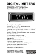
Model PD650 Large Display Process Meter
Instruction Manual
11
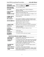
PEAK HOLD
MAX (DISPLAY PEAK)
Captures the maximum or peak process/rate and displays it via
the front panel
ENTER
button
(
Dspy p
)
PEAK HOLD OR
MAX INDICATION
Front panel flashing “
R
” LED
LOCKOUT
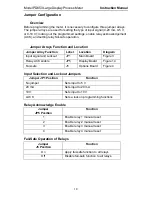
Jumper JP1 labeled “LOCK” restricts modification of
programmed settings.
NON-VOLATILE
MEMORY
All programming values are stored in non-volatile memory for a
minimum of ten years if power is lost.
POWER OPTIONS
AC power: 115 or 230 VAC (field select) ±10%, 50/60 Hz, 12 VA
DC power: 22-28 VDC; 12 watts maximum
NORMAL MODE
REJECTION
64 dB at 50/60 Hz
ENCLOSURE
Die-cast aluminum, NEMA 4X, modified specifically for PDC;
four holes for ½" conduit provided at base, 3 plugs provided.
ENVIRONMENTAL
Operating temperature range: -20 to 65°C
Storage temperature range: -40 to 85°C
Relative humidity: 0 to 90% non-condensing
CONNECTIONS
Removable screw terminal blocks, accept 22 to 12 AWG wire
MOUNTING
Enclosure contains four ¼" holes for wall mounting. Panel
mounting kit available
OVERALL
DIMENSIONS
4.9" x 14.3" x 3.2" (125 mm x 362 mm x 81 mm)
WEIGHT
7.0 lbs (3.2 kg)
WARRANTY
2 years parts & labor
EXTENDED
WARRANTY
1 or 2 years, refer to the Price List for details.
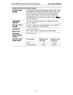
Rate/Totalizer/Batch Controller Features
RATE DISPLAY
INDICATION
LED labeled “
R
” in lower right illuminates when meter is
displaying rate or process input.
LOW-FLOW
CUTOFF
Any input below the low-flow cutoff value will result in a display
of zero. May be set from 1 count to 100% FS, user selectable.
To disable low-flow cutoff, program cutoff value to zero.
Totalizer is based on rate display. So, inputs below the low-
flow cutoff value will not affect the totalizer.
ALTERNATING
DISPLAY
Display may be programmed to alternate between rate and
total every 10 seconds.
TOTAL DISPLAY
0 to 999,999, automatic lead zero blanking
TOTAL DECIMAL
POINT
May be set in any of the following positions: 9.99999, 99.9999,
999.999, 9999.99, 99999.9. Total decimal point is independent
of process/rate decimal point.

