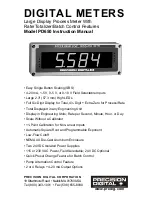
Model PD650 Large Display Process Meter
Instruction Manual
10
Specifications
Except where noted all specifications apply to operation at +25°C.
Basic Process Meter
INPUTS
Field selectable:
4-20 mA, 0-20 mA, 0-5 V, 1-5 V, 0-10 V
DISPLAY
Six digit, 2.3" (57.3 mm) high efficiency red LED.
Rate: -19999(0) to 29,999(0) with selectable extra zero
Total: 0 to 999,999; automatic lead zero blanking
DECIMAL POINT
Process/rate display: Decimal point may be placed in any of the
following positions. 2.9999, 29.999, 299.99, 2999.9, or 299990.
Total decimal point: 9.99999, 99.9999, 999.999, 9999.99, or
99999.9. Rate and total decimal points are independent of each
other.
CALIBRATION
RANGE
4 mA (1 V) input may be set anywhere in range of the meter.
20 mA (5 V) may be set anywhere in range of the meter above
or below 4 mA input. An
Error
message will appear if input 1
signal and input 2 signal are too close together.
Input Range
Minimum Difference Between
Input 1 & Input 2
0-5 V
0.16 V
0-10 V
0.32 V
4-20 mA
1.60 mA
INPUT IMPEDANCE
Voltage ranges: greater than 300 K
Ω
Current ranges: 100
Ω
LOOP POWER
Two isolated power supplies, 24 VDC ± 5% @ 20 mA each,
regulated. Maximum loop resistance is 1200
Ω
.
ACCURACY
Linear input: ±0.05% of calibrated span ±1 count
Root extraction: ±0.1% FS ± 2 counts
ROOT EXTRACTION
Square root extraction: Automatic
Programmable exponent: Greater than 1.0000 and smaller than
3.0000
11-POINT
Input Range
Minimum Span Between Inputs
LINEARIZATION
4-20 mA
(1.6 mA ÷ (Number of points -1))
0-5 V
(0.16 V ÷ (Number of points -1))
0-10 V
(0.32 V ÷ (Number of points -1))
e.g. Minimum span for an 11-point, 4-20 mA calibration is
0.16 mA between inputs.
TIME BASE
Second, minute, hour, or day
ALARM POINTS
Four, any combination of high or low alarms
ALARM POINT
DEADBAND
0-100% of full scale, user selectable
ALARM STATUS
INDICATION
Front panel LED

