background image


P

RO

V

U

 PD6210 Analog Input Batch Controller


Instruction Manual


PRECISION DIGITAL CORPORATION 


233 South Street • Hopkinton MA 01748 USA 

Tel (800) 343-1001 • Fax (508) 655-8990 

www.predig.com


Batch Controller


  0-20 mA, 4-20 mA, 0-5 V, 1-5 V, and ±10 V Inputs 

  Start, Batch, Pause, & Stop with Front Panel Buttons 

  Display Batch Total + Rate, Grand Total, Batch Count or Preset 

  Single or Multi-Stage Batching with up to 8 Relays 

  Automatic Overflow Protection 

  Manual Control or Automatic Batching 

  Dual-Line Display 

  NEMA 4X and IP65 Rated Front Panel 

  UL Listed & CE Marked 

  Display Features 0.6" & 0.46" Digits 

  Six Full Digits on Each Line 

  Optional Superluminous Sunlight Readable Display 

  Free USB Programming Software & Cable 

  2 or 4 Isolated 4-20 mA Output Options 

  External 4-Relay & Digital I/O Expansion Modules 

  Input Power Options Include 85-265 VAC or 12-24 VDC 

  Isolated 24 VDC @ 200 mA Transmitter Power Supply 

  Modbus® RTU Communication Protocol Standard


USB Install

Содержание PD6210-6H2

Страница 1: ...age Batching with up to 8 Relays Automatic Overflow Protection Manual Control or Automatic Batching Dual Line Display NEMA 4X and IP65 Rated Front Panel UL Listed CE Marked Display Features 0 6 0 46 D...

Страница 2: ...s Anyone using this product for such applications does so at his her own risk Precision Digital Corporation shall not be held liable for damages resulting from such improper use Limited Warranty Preci...

Страница 3: ...Setting the Relay Operation relay 31 Relay Assignment Assign 32 Setting the Relay Action 32 Setting Batch Control Relays 32 Programming Alarm Set and Reset Points 33 Setting Fail Safe Operation 33 Pro...

Страница 4: ...uperluminous LED digits make it easily readable in smoke dust fog and with the optional SunBright display even direct sunlight The controller comes programmed for easy front panel start pause stop and...

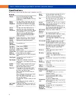
Страница 5: ...210 6H4 PD6210 7H4 4 relays PD1104 PD6210 6H5 PD6210 7H5 2 relays 4 20 mA output PD1105 PD6210 6H7 PD6210 7H7 4 relays 4 20 mA output PD1107 Model number for replacement option card Accessories Model...

Страница 6: ...al Password Prevents resetting the total manually Gtotal Password Prevents resetting the grand total manually Non Volatile Memory All programmed settings are stored in non volatile memory for a minimu...

Страница 7: ...99 9 seconds applied to the first relay assigned to total or grand total If the controller is programmed to reset total to zero automatically when the preset is reached then a delay will occur before...

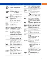
Страница 8: ...wer the 4 20 mA output or other devices Refer to Figure 6 on page 12 and Figure 14 on page 15 All models rated 40 mA max External Loop Power Supply 35 VDC maximum Output Loop Resistance Power supply M...

Страница 9: ...munity standard RFI Amplitude Modulated 80 1000 MHz 10 V m 80 AM 1 kHz 1 4 2 0 GHz 3 V m 80 AM 1 kHz 2 0 2 7 GHz 1 V m 80 AM 1 kHz Electrical Fast Transients 2kV AC mains 1kV other Electrostatic Disch...

Страница 10: ...ry for assistance Panel Mounting Instructions Prepare a standard 1 8 DIN panel cutout 3 622 x 1 772 92 mm x 45 mm Refer to Figure 1 for more details Clearance allow at least 6 0 152 mm behind the pane...

Страница 11: ...e factory configured to provide 24 VDC power for the transmitter or sensor If the transmitter requires 5 or 10 VDC excitation the internal jumper J4 must be configured accordingly To access the voltag...

Страница 12: ...e connectors label affixed to the controller shows the location of all connectors available with requested configuration Warning Do not connect any equipment other than Precision Digital s expansion m...

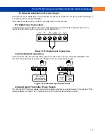
Страница 13: ...voltage inputs Setup and programming is performed through the front panel buttons Figure 7 Transmitters Powered by Internal Supply Figure 8 Transmitter Powered by Ext Supply or Self Powered The curren...

Страница 14: ...loads to prevent disrupting the microprocessor s operation The suppressors also prolong the life of the relay contacts Suppression can be obtained with resistor capacitor RC networks assembled by the...

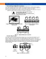
Страница 15: ...signal applied to F4 Figure 13 F4 Digital Input Connections 4 20 mA Output Connections Connections for the 4 20 mA transmitter output are made to the connector terminals labeled MA OUT The 4 20 mA out...

Страница 16: ...ules DIN Rail Mounting Kit Figure 16 External Relays Module Connections Figure 17 Digital I O Module Connections Interlock Relay Feature As the name implies the interlock relay feature reassigns one o...

Страница 17: ...t Panel Buttons and Status LED Indicators Button Symbol Description LED Status Menu 1 8 Relay 1 8 indicators START Right arrow F1 R Rate indicator BATCH Up arrow F2 T Batch Total indicator STOP Enter...

Страница 18: ...r as alarms that will be active when the batch process is running A 4 20 mA output option is also available for retransmitting the process variable analog or pulse signal Default Batch Control Operati...

Страница 19: ...age batch control was desired with one relay for control then one would set the assignment of relay 2 assign2 to off rate or grand total The following pages show an illustration of how the above setti...

Страница 20: ...PROVU PD6210 Analog Input Batch Controller Instruction Manual 20...

Страница 21: ...drive labeled MAINSTAL 3 Double click on the file named MAStart The program will open a few windows and install two programs on your com puter Simply follow the onscreen instructions until you see on...

Страница 22: ...rsion factor Enter the conversion factor decimal point and the conversion factor mode Batch mode Automatic or manual batch control T dly Time delay Set time delay for automatic batch restart GT tb Gra...

Страница 23: ...tput 1 Program output 1 value e g 4 000 mA Dis 2 Display 2 Program display 2 value Out 2 Output 2 Program output 2 value e g 20 000 mA reset Reset Press Enter to access the Reset menu Rst Hi Reset hig...

Страница 24: ...gs are saved to memory only after pressing Enter The display moves to the next menu every time a setting is accepted by pressing Enter Setting Numeric Values The numeric values are set using the Right...

Страница 25: ...totalizer and batching features 3 Select the display units tags 4 Decimal point position 5 Program menu for scaling or calibration 6 Display parameter and intensity 7 Relay operation 8 4 20 mA analog...

Страница 26: ...features and functions are hidden from the menus Setting the Input Units or Custom Tags units Enter the input unit or custom tag that will be displayed if alternating rate total or grand total and uni...

Страница 27: ...librated or scaled to any display value within the range of the controller Additional parameters not needed for most applications are programmed in the Advanced Features menu see ADVANCED OPERATION AN...

Страница 28: ...e error message is displayed the controller reverts to input 2 during calibration or scaling and to input 1 during internal calibration allowing the appropriate input signal to be applied or programme...

Страница 29: ...lly stopped batch will require a manual start to begin a new batch process Grand Total Reset The grand total can be programmed for manual or automatic reset In the automatic reset mode a programmable...

Страница 30: ...min values 5 Display Modbus input 6 Off no display 7 Display rate units 8 Display rate 9 Display total 10 Display grand total 11 Toggle rate and total 12 Toggle rate and grand total 13 Display batch c...

Страница 31: ...cess only after alarm condition has cleared e Pump alternation control automatic reset only for level applications unrelated to batch control f Sampling the relay is activated for a user specified tim...

Страница 32: ...te for batch control applications but may be used then the controller is in other applications 4 Automatic manual reset when not in a batch process non latching 5 Latching manual reset only when not i...

Страница 33: ...for each relay Select on to enable or select off to disable fail safe operation Failsafe mode should not be used on batch relays assigned to total Programming Time Delay The On and Off time delays may...

Страница 34: ...ir programmed states when the batch process is started Grand total alarm relays will initialize to their programmed state at controller power up Fail Safe Operation The following table indicates how a...

Страница 35: ...as interlock relays To set up the relays for the interlock feature 1 Access the Setup Relay Action menu and set the action to off 2 In the Advanced features User menu program any of the digital input...

Страница 36: ...diagram below for more details The utility of this function can of course be expanded beyond sampling and be used whenever a timed relay output closure is required when the batch total interval reach...

Страница 37: ...conds Total Relay Sampling Operation When the batch total reaches the set point the relay trips and the sample time starts After the sample time has elapsed the relay resets The cycle repeats every ti...

Страница 38: ...same principle applies to the Off time delay Note If Automatic or Manual A mAn reset mode is selected the LED follows the reset point and not the relay state when the relay is acknowledged Scaling th...

Страница 39: ...elays and analog output for automatic operation Setting Up the Password pass The Password menu is used for programming three levels of security to prevent unauthorized changes to the programmed parame...

Страница 40: ...the menu After exiting the programming mode the controller returns to its password protected condition Disabling Password Protection To disable the password protection access the Password menu and ent...

Страница 41: ...tures or make running a batch operation impossible These functions should only be used by users who are sure of their need in their application Advanced Features Menu To simplify the setup process fun...

Страница 42: ...onent Set controller for programmable exponent and enter exponent value CutofF Cutoff Set low flow cutoff Count Count Set the totals to count up or down from a set value Tot C Total count Set the batc...

Страница 43: ...signal source C CAL Current calibration Calibrating 4 20 mA current input internal reference source used for scaling the input C lo Current low Calibrate low current input e g 4 mA Display Parameter...

Страница 44: ...min max display manual alarm reset or total reset will function while a batch is running Advanced Setup and Calibration Multi Point Calibration Scaling The controller is set up at the factory for 2 po...

Страница 45: ...nals Rounding is used in addition to the filter function Rounding causes the display to round to the nearest value according to the rounding selected This setting affects the last two digits regardles...

Страница 46: ...ransmitter and display flow rate in engineering units Programmable Exponent Linearization Prog E The programmable exponent can be used to linearize the signal from level transmitters in open channel f...

Страница 47: ...ned to the rate process variable total grand total maximum or minimum value reached by the rate process one of the set points or the Modbus PV input Analog Output Calibration To perform the analog out...

Страница 48: ...Display maximum minimum dis play values on line 2 Ln2 gt Display the grand total on line 2 Ln2 bc Display the batch count on line 2 Contrl Directly access the control menu Display Description disabl...

Страница 49: ...w input signal 5 After the display stops flashing a number is displayed with the leftmost digit brighter than the rest The bright digit is the active digit that can be changed by pressing the Up arrow...

Страница 50: ...ersion To determine the software version of a controller 1 Go to the Diagnostics menu diAG and press Enter button 2 Press Up arrow button and scroll to Information menu Info 3 Press Enter to access th...

Страница 51: ...base GT tb Second Grand total conversion factor T CF 1 000 Grand total reset T rst Manual Relay 1 assignment Asign1 Total Relay 2 assignment Asign2 Total Relay 2 preclose preCls No Relay 3 assignment...

Страница 52: ...CutofF 0 000 disabled Maximum output mAx 23 000 mA Minimum output min 1 000 mA Slave ID Address Slave Id 247 Parameter Display Default Setting Baud rate baud 9600 Transmit delay Tr dly 50 ms Parity Pa...

Страница 53: ...or calibration Display does not respond to input changes reading a fixed number Check Display assignment it might be displaying max min or set point Display alternates between 1 Hi and a number 2 Lo a...

Страница 54: ...PROVU PD6210 Analog Input Batch Controller Instruction Manual 54 This Page Intentionally Left Blank...

Страница 55: ...cable technical standards and when applicable or required a European Union notified body certification Standards EN 55022 2003 EN 61000 6 2 2001 EN 61010 1 2001 EN 61326 2006 The standards EN 55022 20...

Страница 56: ...0_F SFT039 Ver 4 010 up 03 17 How to Contact Precision Digital For Technical Support please Call 800 610 5239 or 508 655 7300 Fax 508 655 8990 Email support predig com For Sales Support or to place an...

Отзывы: