Chapter 4 Installation and commissioning
25
Ch
ap
ter 4
+24V
COM
PLC
(Default)
DI1
DI8
COM
PLC
PE
Shielded
cable
Inverter
Inner power NPN connect mode
External
contactor
+24V
COM
PLC
(Default)
DI1
DI8
COM
PLC
PE
Shielded
cable
Inverter
External power supply NPN connect mode
External
contactor
External
power supply
+
-
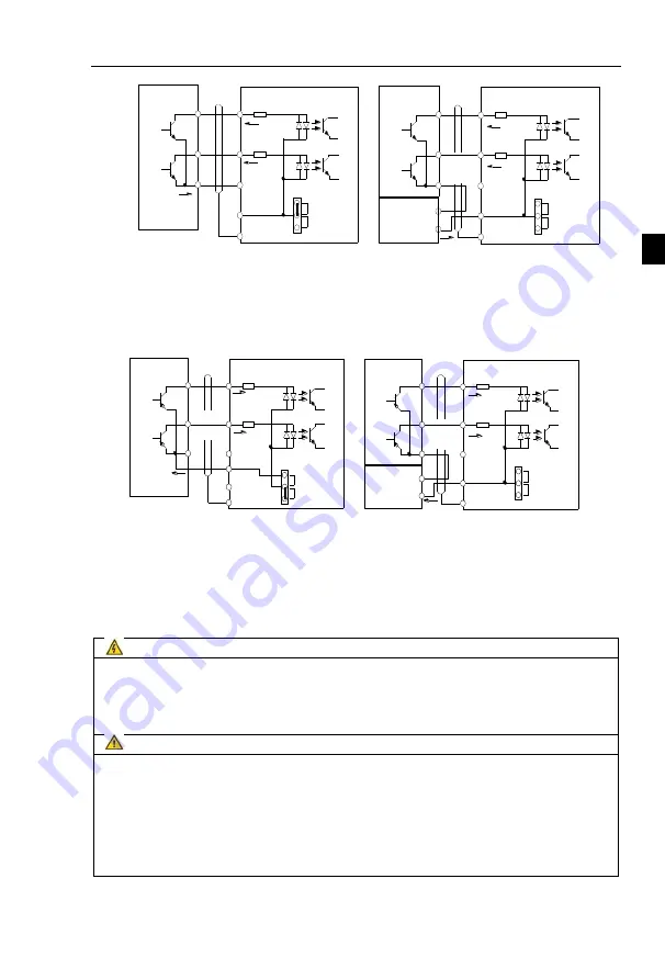
Figure 4-17
:
Signal input terminal wiring diagram, open collector NPN connection mode
Note: using an external power supply, PLC and 24 v jumper cap must be removed, otherwise
it will damage the product.
Open collector PNP connection mode:
+24V
COM
PLC
(Default)
DI1
DI8
COM
PLC
PE
Inverter
Inner power PNP connect mode
External
contactor
+24V
COM
PLC
(Default)
DI1
DI8
COM
PLC
PE
Shielded
cable
Inverter
External power supply PNP
connect mode
External
contactor
External
power supply
+
-
+24V
Figure 4-18
:
Signal input terminal wiring diagram, open collector PNP connection mode
Note: using an external power supply, PLC and 24 v jumper cap must be removed, otherwise
it will damage the product.
4-5.
Wiring Precautions
Danger
Make sure that the power switch is in the OFF state before wiring operation, or electrical shock
may occur!
Wiring must be performed by a professional trained personnel, or this may cause damage to the
equipment and personal injury!
Must be grounded firmly, otherwise there is a danger of electric shock or fire hazard !
Note
Make sure that the input power is consistent with the rated value of inverter, otherwise which
may cause damage to the inverter!
Make sure that the motor matches the inverter, otherwise which may cause damage to the
motor or activate the inverter protection!
Do not connect power supply to U, V, W terminals, otherwise which may cause damage to the
inverter!
Do not directly connect braking resistor to DC bus (P), (+) terminals, otherwise which may
cause a fire!
※
The U,V,W output end of inverter can not install phase advancing capacitor or RC absorbing
device. The inverter input power must be cut off when replacing the motor


