


page no. 26 of 68
CP
x Range Users, Installation & Servicing Instructions Doc Ref M201 issue 2.9 Nov 2018.
These are equipped with rotatable air delivery heads fixed
to the top panel of the unit providing rotational and lateral
direction. The quantity of heads depend on the heater size
(see Head Plans in section 1.2) and consist of a number
of standard and extended heads. Extended heads are
placed on the rear of the heater when located adjacent to
a wall to allow complete freeblowing access without any
restrictions.
NOTE: We do not recommend removing and
blanking off any of these heads or removing
singular heads and replacing with similar sized
spiral ductwork. Ducted units are available for
these applications.
For free-blowing units installed in buildings having a low
heat loss i.e. where single units are required to cover a
large floor area, and in buildings with high roof or ceiling
heights Calecon thermal economiser units should be
fitted to ensure even heat distribution and minimise
stratification.
Care should be taken to avoid impeding the heater air
throw with racking, partitions, plant or machinery etc.
Various outlet configurations are available as optional
extras to modify the air throw pattern to suit particular
site conditions.
These are designed for use with duct work to more
precisely define the point of air delivery, and /or provide
ducted return air or ducted fresh air inlet.
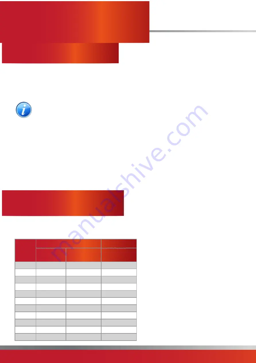
Ductwork must be specially calculated to comply with the
maximum static resistance available for the specific model
installed. (see table)
If fitting horizontal ductwork, it is recommended that a
plenum box with the same external dimension as the duct
spigot with a minimum height of 1.0m be fitted to the
heater outlet spigot to allow for even distribution of air.
If fitting vertical ductwork it is recommended that a
plenum box with the same external dimension as the
duct spigot with a minimum height of 1.0m be fitted to
heater outlet spigot prior to any restriction in ductwork. All
ducting must be independently supported of the air heater.
All delivery and return air ducts, including air filters,
jointing and any insulation or lining must be constructed
entirely of materials which will not contribute to a fire,
are of adequate strength and dimensionally stable for the
maximum internal and external temperatures to which
they are to be exposed during commissioning and normal
operation.
Where inter-joist spaces are used as duct routes they
should be suitably lined with a fire-resisting material.
A full and unobstructed return air path to the air heater(s)
must be provided. If the air heater(s) is installed in a plant
room the return air intake(s) and the warm air outlet(s)
from the heater(s) must be fully ducted, into and out of the
plant room to avoid interference with the operation of the
heater from other equipment.
The openings in the structure of the plant room through
which the ducting passes must be fire stopped. Care must
be taken to ensure that return-air intakes are kept clear
of sources of smells and fumes, and where there is any
possibility of pollution of the air by dust, shavings etc.,
precautions must be taken to prevent contamination.
If necessary suitable barrier rails should be
provided to prevent any combustible material
being placed within 900mm of the outlets.
Joints and seams of supply ducts and fittings must
be securely fastened and made airtight.
It is recommended that ducting should be
connected to the heater spigots via an airtight
flexible coupling of noncombustible material.
Before fitting coupling it must be ensured that an
adequate clearance will be maintained between
the ends of the ducting and the heater spigots.
If required sound attenuators may be fitted in
inlet and outlet ducts to reduce airborne fan noise.
Materials used in outlet sound attenuators must
be capable of withstanding 100°C air temperature
without any deterioration.
Model
Standard Motor
LHP Motor
Air Volume
(m³/s)
Max Duct
Resistance (Pa)
Max Duct
Resistance (Pa)
CPx30
0.97
188
250
CPx45
0.86
222
250
CPx60
1.01
270
400
CPx90G
2.11
250
500
CPx90O
1.5
200
450
CPx120
2.3
180
350
CPx150
3.15
185
400
CPx175
3.36
290
500
CPx200
3.84
250
500
CPx250
4.49
140
450
CPx300
5.76
150
500


