


2--28
Powerware BPIV (10 kVA--30 kVA) Installation and Operation
164201406 Rev. C 013004
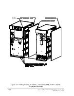
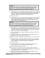
13.
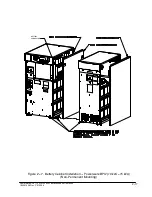
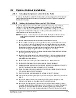
Remove the top side panel mounting screw (tie/grounding bracket location in
Figures 2---11 or 2---13) from both the Option and UPS cabinets.
14.
Secure the back of Options cabinet to the back of the UPS cabinet with the
tie/grounding bracket. Secure the bracket with the side panel mounting
screws.
15.
Proceed to paragraph 2.4.3.
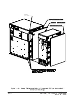
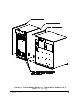
16.
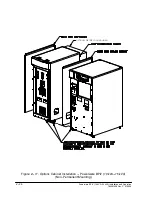
Using retained hardware, reinstall shipping brackets previously removed to
front and rear of Options cabinet with the angle facing outward.(see Figures
2---12 or 2---14).
17.
Secure the front of Options cabinet to the front of the UPS cabinet with the
long flat grounding/mounting bracket from the installation kit (see Figures
2---12). Use hardware provided in the kit to secure the bracket.
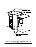
18.
Remove the top side panel mounting screw (tie/grounding bracket location in
Figure 2---12 or 2---14) from both the Option and UPS cabinets.
19.
Secure the back of Options cabinet to the back of the UPS cabinet with the
tie/grounding bracket. Secure the bracket with the side panel mounting
screws.
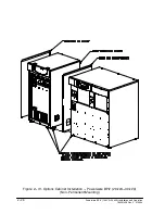
20.
Secure cabinets to floor with contractor supplied hardware.
21.
Proceed to paragraph 2.4.3.
2.4.3
Installing Options Cabinet Internal and UPS Optional Remote
Battery Power Wiring
1.
If not already removed, remove left front solid panel and right front vented
panel from the Powerware BPIV (10 kVA---15 kVA) UPS cabinet or left front
solid panel and front vented panels from the Powerware BPIV (20 kVA---30
kVA) UPS cabinet. Front panels are secured with magnetic latches and are
removed by pulling panels straight forward to disengage magnetic latches (see
Figure 2---1 or 2---5).
2.
Remove screws securing internal safety shield panels and remove panels to
gain access to input and output terminals.
NOTE:
Remove UPS cabinet input, output, and remote battery input conduit landing
plate to punch conduit holes.
3.
If wiring an optional remote battery system, proceed to step 4; otherwise
proceed to step 6.
CAUTION:
When sizing battery system, do not exceed internal battery charger
capabilities. Refer to Chapter 15
“Specifications”
, for maximum battery charger
currents.
4.
Route battery cables from the remote battery system to UPS Remote Battery
Terminal Block. Refer to Appendix A of this manual for wiring access
information.
Содержание BPIV
Страница 1: ...www powerware com BPIV INSTALLATION OPERATION MANUAL UPS 10 15 kVA 20 30 kVA...
Страница 19: ...Powerware BPIV 10 kVA 30 kVA Installation and Operation 164201406 Rev C 013004 Section I Installation...
Страница 79: ...Powerware BPIV 10 kVA 30 kVA Installation and Operation 164201406 Rev C 013004 Section II Operation...
Страница 104: ...8 10 Powerware BPIV 10 kVA 30 kVA Installation and Operation 164201406 Rev C 013004 This Page Intentionally Left Blank...
Страница 128: ...9 24 Powerware BPIV 10 kVA 30 kVA Installation and Operation 164201406 Rev C 013004 This Page Intentionally Left Blank...
Страница 138: ...10 10 Powerware BPIV 10 kVA 30 kVA Installation and Operation 164201406 Rev C 013004 This Page Intentionally Left Blank...
Страница 142: ...11 4 Powerware BPIV 10 kVA 30 kVA Installation and Operation 164201406 Rev C 013004 This Page Intentionally Left Blank...
Страница 174: ...15 4 Powerware BPIV 10 kVA 30 kVA Installation and Operation 164201406 Rev C 013004 This Page Intentionally Left Blank...
Страница 262: ...W 2 Powerware BPIV 10 kVA 30 kVA Installation and Operation 164201406 Rev C 013004 This Page Intentionally Left Blank...
Страница 263: ......
Страница 264: ...164201406 Rev C 164201406C...


