14
2-6-3. Parallel Function Setting
1.
For the input and output wiring, please be sure to follow the instruction in section 2-6-1.
2.
For the parallel board setting, please be sure to follow the instruction in section 2-6-2.
Once the two steps above have been completed correctly, and then set parallel function and battery
configuration. Proceed with the following steps:
1.
Do not connect Parallel Cable until informed.
2.
Place the input breakers (Q1) of two UPSs to the “ON” position. But keep the output breakers
(Q3) of two UPSs in the “OFF” position.
3.
Turn on the battery breaker.
4.
Turn on the external AC source breaker to apply AC input source to both UPS.
5.
Wait for the completion of power-cycles. Proceed to set UPS 1.
6.
Set up the parallel function through the LCD panel on UPS 1. Enter the “PARALLEL” menu in
“SETUP” page. (Refer to User Manual 3-2-5-5. Setup-Parallel Screen)
7.
Enable “UPS Parallel” function of UPS 1. (Ignore the warning of “Parallel UPS Cable
Loosen”)
8.
Choose the battery configuration as “independent” or “common” battery, depending on your
preference.
9.
Select the “Save Setting” icon in “General” screen of “SETUP” page to save your settings.
10.
Proceed to set up UPS 2.
11.
Setup the parallel function through the LCD panel on UPS 2. Enter the “PARALLEL” menu in
“SETUP” page. (Refer to User Manual 3-2-5-5. Setup-Parallel Screen)
12.
Enable “UPS Parallel” function of UPS 2. (Ignore the warning of “Parallel UPS Cable
Loosen”)
13.
Choose the battery configuration as “independent” or “common” battery, depending on your
preference.
14.
Select the “Save Setting” icon in “General” screen of “SETUP” page to save your settings.
15.
Turn off the external AC source breaker and wait for complete shutdown of both UPS.
16.
Turn off battery breakers.
2-6-4. Parallel Cable Connection
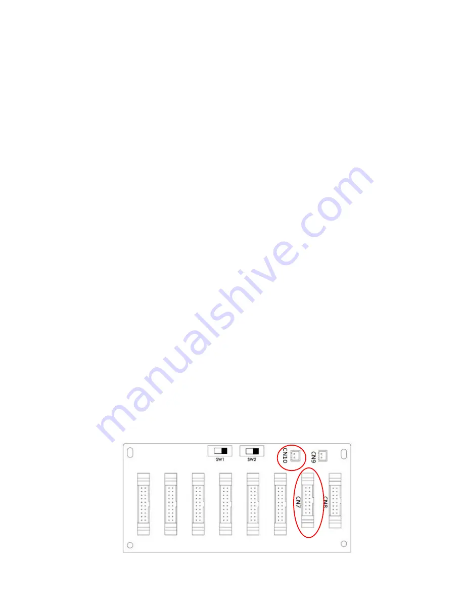
There are two connectors at the end of each parallel cable. One is a 16-pin connector and the other is a
2-pin connector. Insert the 16-pin connector into the CN7 port of UPS 1 and 2-pin connector into the CN10
socket of UPS 2 and vice versa. Please refer to below figures for details.
For the UPS with two parallel boards, use any one of two boards.
UPS 1 Parallel Board
Содержание VFI 100K CPG 3/3 BX
Страница 1: ...PowerWalker VFI 100 200K CPG 3 3 Manual Uninterruptible Power Supply System Version 1 1...
Страница 4: ...1 8 1 STORAGE 59 8 2 MAINTENANCE 59 9 SPECIFICATIONS 60...
Страница 50: ...46 Maintenance Bypass Mode Diagram...
Страница 59: ...55 After turning off the UPS will tranfer to Standby Mode...


