


powersoft_dcell504_uguide_en_v4.0
www.powersoft-audio.com
26
D-Cell504
User Guide
Example 2: Probe and Stimulus Blocks
Complete the first example in order for an explanation of the input, output, and EQ blocks that are used in this tutorial.
Its purpose is to show you how to use probe and stimulus blocks to monitor the frequency response of the filters you set.
1) Insert an
Input
from the
IO
tab of the ToolBox.
2) Click the
System
tab and drag two
Stimuliblock
blocks to the
workspace.
3) Connect wires from the input channels to the Stimuliblock block.
4) Insert two
Medium Size Eq
blocks from the
Filters
tab.
5) For each EQ block, right-click and select
Add Algorithm > IC 1
> Single - Double Precision
.
6) Right-click each again and select
Grow Algorithm > 1. Single -
Double Precision > 2
.
7) Connect wires from the output of the Stimuliblock block to the
input of the EQ block.
8) Click the
System
tab and drag one
Probeblock
block into your
workspace.
9) Right-click the block and select
Add Pins
.
10) Connect wires from the output of the EQ to the input of the Probeblock.
11) Click the
IO
tab and drag two
Output
blocks into the workspace.
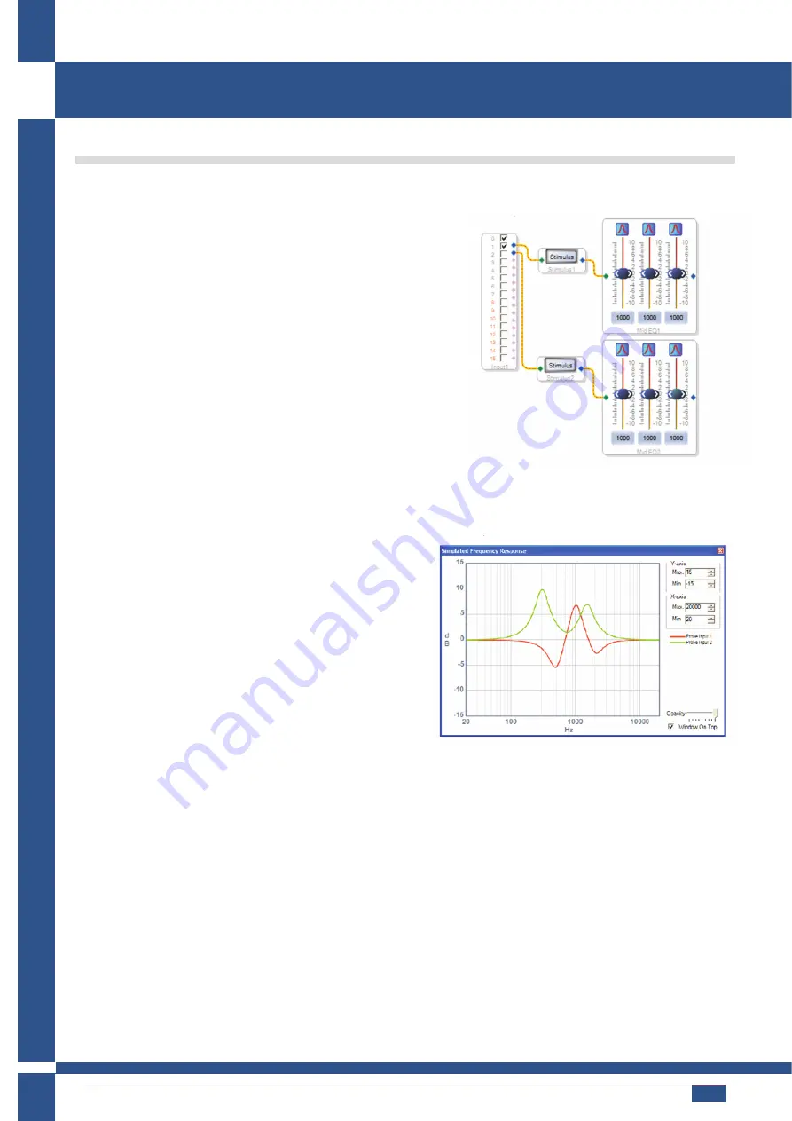
12) Connect wires from the output of the probes to the input of the Output block. Your workspace should look like this:
Compile the project: Click
Link Compile Download
on the
toolbar or select
Action
,
Link Compile Download
.
13) Click the
Probe
block to bring up the Simulated
Frequency Response window. There will be nothing
displayed.
14) Click the
Stimulus
block buttons to bring up the
Frequency Response window. You can now view in real
time any changes you make to the EQ. The response for
the above parameters is shown here:
Содержание D-Cell504 IS
Страница 18: ......


