


3-25
PFC-6030 • 5403595 • REV C-1 • 10/13
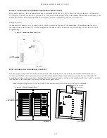
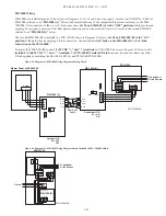
P-Link Devices
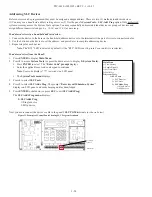
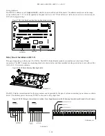
Accessory devices, such as remote and LED annunciators, and a relay expander (RLY-5), are connected to the main control panel
utilizing the four-wire P-Link bus for power and communication. This panel supports a maximum of
64 P-Link devices,
which
can
be connected using a Class B or Class A wiring style (examples are provided throughout this topic).
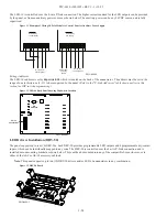
Note
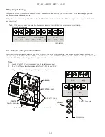
: If you have chosen to install an optional PSN-1000/PSN-1000(E) power expansion board, refer to
Section 6:
PSN-1000/PSN-1000(E) – Installing, Operating & Programming,
for instructions on installing this appliance.
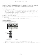
Configuration Characteristics
y
y
P-Link current rating is one (1) amp.
y
y
P-Link voltage rating is 24 VDC.
y
y
The maximum wire length is 6,500 feet.
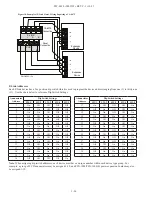
Maximum Wire Resistance Formula
The maximum resistance is based on the
load
placed on the circuit. To calculate the maximum wire resistance, use the following
formula:
(Total Annunciator Alarm Current) x (Wire Resistance) < 6 Volts
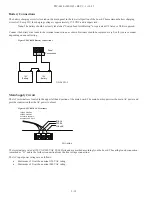
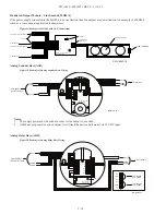
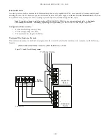
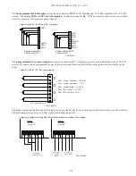
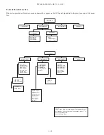
Figure 27. P-Link Class B Wiring Example
To the next device
-
+
A
B
Expansion
Device
-
+
A
B
P-LINK
-
+ A B
Panel
Connection
Expansion
Device
DWG #602-11A


