


2-11
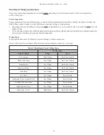
PFC-6030 • 5403595 • REV C-1 • 10/13
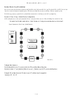
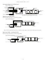
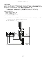
Scenario 2: Class B Loop – Isolated Branch Configuration
In this configuration, there are 4 separate branches each with an isolation device / module and 1 or more sensors. Each sensor
requires an address, as shown in Scenario #1 (isolators do not require an address). However, in this scenario, each isolator
consumes power equal to 8 devices. To calculate the total device load, refer to the following rule:
Device Load Rule for Branch Configurations
Count all devices, including isolators, on the branch.
• If the count is <=8, allocate 8 as the device load.
• If the count is >8, allocate the actual device count number.
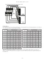
Figure 4. Example of a Class B Loop – Isolated Branches
Configuration Summary:
Branch #1 has 3 devices = 8 power allocations
Branch #2 has 2 devices = 8 power allocations
Branch #3 has 10 devices = 10 power allocations
Branch #4 has 4 devices = 8 power allocations
Total addressable devices = 15 (sensors only) out of 30 addressable points.
Total device load = 34 out of a possible 127 power unit allocations.
LEGEND:
ISO Module/
Device
Sensor
BRANCH #1
BRANCH #2
BRANCH #3
BRANCH #4
PANEL
Total devices = 3
Total devices = 2
Total devices = 10
Total devices = 4
DWG #593-3


