background image


User manual 


PONSEL 

Référence : NOTICE_ACTEON_2050_v001  

V : 002 

43/67 


9.3  Adjusting SS sensor offset 

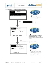
You must adjust the SS sensor offset when activating or changing the SS sensor. This operation should be 
carried out only once. 


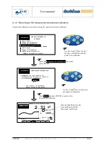
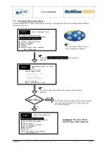
Use the 

and

keys to select 

the configuration required. 


Select the 

 Sensor offset adjustment

 menu and press 

ENTER.


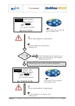
Cover the optical slot with a dark coloured ruler and press 
ENTER. 

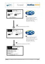
CONFIG 

WHAT DO YOU WANT TO DO? 


ESC: Escape menu 

 Averaging sensor response 

 Sludge slope coefficient reminder 

 Sensor offset adjustment 

 Graphic screen 

 4-20mA outputs adjustment 

 Relay adjustment  

 Measure units 

 Language 

 Factory default value reminder 

CONFIG 

EXTINCTION OF THE I.R. LIGHT 
BEAM 

    Occult the optical slot 
      with an opaque ruler 
 
        Sensor offset:   12mV 


DO NOT VALIDATE 

         Extinction incomplete! 

ESC: Escape menu


Enter: Validate and record


If the offset is too high check that the dark coloured 
ruler is positioned properly over the optical slot 
(see following page) 
  

No 

Yes 

CONFIG 

WHAT DO YOU WANT TO DO? 


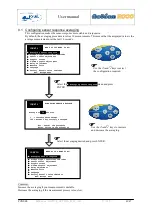
 Averaging sensor response 

 Sludge slope coefficient reminder 

 Sensor offset adjustment 

 Graphic screen 

 4-20mA outputs adjustment   

 Relay adjustment  

 Measure units 

 Language 

 Factory default value reminder 

ESC: Escape menu 


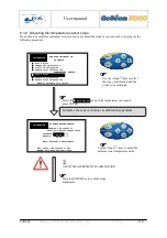
Offset Correct


Comment: SS sensor offset 
has been correctly adjusted. 

Содержание ACTEON 2000 Series

Страница 1: ...NSEL Référence NOTICE_ACTEON_2050_v001 V 002 1 67 WRITTEN BY REVIEWED BY APPROVED BY NAME STÉPHANE LE GUYADER NAME PIERRE PECCHIA NAME YVAN BOUDEY SIGNATURE SIGNATURE SIGNATURE ACTEON 2050 SS Temperature User manual ...

Страница 2: ...ersonnel duly authorised by the end user Trained personnel must be familiar with and comply with the instructions in this activation manual Make sure the power supply complies with the specifications on the nameplate before connecting the device A clearly labelled power switch must be positioned near the device Check all connections before turning the power on Do not use damaged equipment it may r...

Страница 3: ...ch ref PONPPCC CIR or Straight Sensor Holder Perch ref PONPPCD CIR on QRPM ref PONSPFR and PONSPFR2 13 2 4 In pipe installation 14 3 ACTEON 2050 TRANSMITTER 15 3 1 Control console 15 4 BLOCK DIAGRAM OF ACTEON 2050 MENUS 16 5 THE MEASUREMENT WINDOW 17 6 CALIBRATING THE ACTEON 2050 18 6 1 Calibrating the sensors 19 6 1 1 Two point SS sensor calibration immediate calibration 19 6 1 2 Two point SS sen...

Страница 4: ...ay outputs 51 9 6 1 Configuring relays in mode 1 52 9 6 2 Configuring relays in mode 2 52 9 6 3 Configuring relays in mode 3 52 9 7 Adjusting measurement units 52 9 8 Setting the language 52 9 9 Resetting factory default values 52 10 INFORMATION MENU 52 11 ADJUSTING THE ACTEON 2050 DISPLAY CONTRAST 52 12 TECHNICAL SPECIFICATIONS 52 13 SENSORS 52 13 1 SS sensor 52 13 1 1 Specifications 52 13 1 2 Me...

Страница 5: ... measuring system 9 Figure 3 Installation with a connection box 10 Figure 4 Transmitter mount and hood 11 Figure 5 Elbowed Sensor Holder Perch 12 Figure 6 Installing a perch on a QRPM with one or two sliders 13 Figure 7 SS sensor in pipe installation 14 Figure 8 Resetting ACTEON 2050 52 Figure 9 Transmitter wiring terminal layout 52 ...

Страница 6: ...Thermometer transmitter 0 00 20 00g l range MES5 sensor PONACTEON2050 50 ACTEON 2050 50 SS meter and Thermometer transmitter 0 00 50 00g l range MES5 sensor 1 1 2 A SS sensor PONCIR MES5 10 IR optical sensor for suspended solids measurements with 10 metre cable connection and 5mm optical length Perch mounting or in pipe installation PVC body 1 1 3 Temperature sensor PONCPC T 10 Temperature sensor ...

Страница 7: ...ONPPCC CIR PVC elbowed sensor holder perch for SS sludge blanket CTZ NTU and TU20 sensors Supplied with connector PONPPCD CIR PVC straight sensor holder perch for SS sludge blanket CTZ NTU and TU20 sensors Supplied with connector SPECIFIC APPLICATION PONCOUDE 90 elbow for sensor holder perch closure PONSPFR2C Stainless steel ESHP or SSHP type mount for 2 perches 1 arm 2 sliders PONSPFR1C Stainless...

Страница 8: ...PONSEL Référence NOTICE_ACTEON_2050_v001 V 002 8 67 2 Installation 2 1 Mounting the ACTEON 2050 transmitter box Acteon 2050 mounting diagram A B C Dimensions mm 156 5 181 195 3 Figure 1 Transmitter mounting diagram ...

Страница 9: ...talling a measuring system Comment If the connection cable between the sensor and transmitter is longer than 10 metres a watertight IP 68 connection box must be used REF PON BJ E Relay cable 2 channels 4 20mA cable 2 channels Power supply cable 230V or 24VDC Line out cable 1 5 2 3 1 2 3 4 4 SS sensor PONCIR MES5 10 5 6 Temperature sensor PONCPC T 10 6 ...

Страница 10: ...th a connection box 2 2 1 Acteon 2050 wiring See appendix 15 at the end of the document Relay cable 2 channels 4 20mA cable 2 channels Power supply cable 230V or 24VDC Line out cable 1 5 2 3 1 2 3 4 4 SS sensor PONCIR MES5 10 5 6 Temperature sensor PONCPC T 10 6 7 7 Connection box PON BJ E ...

Страница 11: ...rotective hood A PVC protective hood PON PDPVC 1 is available for mounting the ACTEON 2050 The hood is essential in the case of direct exposure to adverse weather or sunshine Figure 4 Transmitter mount and hood 2 3 2 Installing the sensor in the sensor holder perch elbowed or straight PONPPCC CIR or PONPPCD CIR ...

Страница 12: ...ection making it submersible up to a several bars of pressure 1 Completely unscrew the tightening seal located on the sleeve of the SS sensor beforehand 2 Pass the sensor cable through the bottom of the perch widest end until it comes out of the other end 3 Slide the cable through the perch until the SS sensor sleeve fits into the bottom of the perch 4 Slot the SS sensor sleeve insert in the later...

Страница 13: ... PONPPCD CIR on QRPM ref PONSPFR and PONSPFR2 1 Fix the stainless steel QRPM to the infrastructure 2 Next fix a sensor holder perch to the stainless steel QRPM as shown in the diagram below Figure 6 Installing a perch on a QRPM with one or two sliders A second slider may be added to install a second sensor holder perch for the temperature sensor see diagram above ...

Страница 14: ...pipe 20 bars with quick release conical coupling clamps see Figure 7 SS sensor in pipe installation Figure 7 SS sensor in pipe installation Closed conical clamps Connector attached View from above Tightening screw 2 conical clamps External weld Pipe MES5 Sp sensor for in pipe installation with a quick mounting dismounting system using conical clamps ...

Страница 15: ...ssing menus or confirming actions 2 ESC key for exiting menus or cancelling actions 3 key for moving left in menus 4 5 key for moving right in menus key for increasing a value or selecting the menu above 6 The key for decreasing a value or selecting the menu below 8 Quarter turn screw to seal the cover 2 5 3 4 6 8 7 7 Control screen ...

Страница 16: ...mA and 20mA stop switches 9 5 1 4 20mA output calibration 9 5 2 Threshold adjustment in mode 1 9 6 1 Threshold adjustment in mode 2 9 6 2 Factory default configuration reminder 9 9 Gain adjust 6 1 3 Differed calibration 6 1 2 Theoretical calibration 6 1 4 Gain adjust 6 1 6 Complete calibration 6 1 5 Theoretical calibration 6 1 7 SS sensor Temperature sensor Immediate calibration 6 1 1 Averaging se...

Страница 17: ...calibration point on the probe 6 Temperature transmitted by the temperature sensor In the event of faulty wiring or uninstalled sensor the temperature will not be displayed Comment The following icon is displayed if the temperature is higher than the operating temperature 55 C 3 No icon displayed means that the last calibration is correct Mode1 4 R1 and R2 relays state and operating mode ACTEON me...

Страница 18: ...r in situ attached to a perch and placed in the measurement medium at the point where it will subsequently be installed for regular measurements The sludge content in g l may already have been measured for this point immediate calibration or gain adjust menus for instance by using a recently calibrated reference SS meter or sludge may be taken from near the optical measurement unit and analysed wh...

Страница 19: ...he remaining amount at 4 C in an airtight bottle in the dark to prevent fermentation Once the analysis results have been obtained the sludge can be used as calibration solution during this immediate calibration procedure provided that it is brought up to tank temperature Clean the SS sensor beforehand The sensor optics must be free of dirt and stains clean optical slit with damp cloth See MAINTENA...

Страница 20: ...libration menu and press ENTER Use the and keys to move the cursor in the name section Use the keys and to change the letters The scrolling order of the letters is A Z 0 9 space Enter your name or reference then press ENTER CALIBRATION OF SS SENSOR ESC Cancel the procedure ENTER Start calibration Enter your name Durant Dip the sensor in clean water with no bubbles tap water for example Preferably ...

Страница 21: ...um enough to immerse the sensor in a 5 litre pail or larger Dip the sensor in the half filled pail of sludge and keep stirring gently to prevent decanting and to keep the SS in suspension as much as possible Advice The sample sludge must remain at the temperature of the tank and must not be active calibrate immediately after sample taking Calibration Correct If the first calibration point is incor...

Страница 22: ...tep consists in zeroing the sensor in CLEAN water then measuring and recording the infrared emission in your unidentified sludge sample Send a fraction of this sample for analysis while carrying out the first step If the second calibration point is incorrect an error message window appears see Error message information chapter 6 2 2 Calibration Correct No Yes Comment The measurement window is disp...

Страница 23: ... Immediate calibration menu then press ENTER Use the and keys to move the cursor in the name section Use the keys and to change the letters The scrolling order of the letters is A Z 0 9 space Enter your name and reference and press ENTER CALIBRATION SS SENSOR ESC Cancel the procedure ENTER Start calibration Enter your name Durant Dip the sensor in clean water with no bubbles tap water for example ...

Страница 24: ...litre pail or larger Dip the sensor in the half filled pail of sludge and keep stirring gently to prevent decanting and to keep the SS in suspension as much as possible Advice The sample sludge must remain at the temperature of the tank and must not be active calibrate immediately after sample taking Calibration Correct If the first calibration point is incorrect an error message window appears se...

Страница 25: ... SENSOR Gain adjust Immediate calibration Content of SS after analysis Theoretical calibration TEMPERATURE SENSOR Gain adjust Complete calibration Theoretical calibration ENTER Validate the choice Use the and keys to select the type of calibration and the probe to be calibrated Select the Content of SS after analysis menu and press ENTER Comment The measurement window is displayed again once the c...

Страница 26: ...urrent slope coefficient 100 New slope coefficient 120 Comment The measurement window is displayed again once the calibration has been correctly carried out 20 00 C 24 hrs 5 00 MEASURE g l INFO CONF HIST CAL LOG MEAS Mode1 R1 R2 ACTEON 2050 20 Turbidimeter g l 1 6 If the second calibration point is incorrect an error message window appears see Error message information chapter 6 2 2 Calibration Co...

Страница 27: ...idate the choice CALIBRATION SENSORS CALIBRATION SS SENSOR Gain adjust Immediate calibration Differed calibration Theoretical calibration TEMPERATURE SENSOR Gain adjust Complete calibration ENTER Validate the choice CALIBRATION OF SS SENSOR Immerse the sensor in your SLUDGE g l g l ESC Leave the current slope ENTER Validate the new slope 5 00 4 20 WAIT Nonstable measurement Current slope coefficie...

Страница 28: ...an error message window appears see Error message information chapter 6 2 2 Calibration Correct No Yes Comment The measurement window is displayed again once the calibration has been correctly carried out 20 00 C 24 hrs 2 31 MEASURE g l INFO CONF HIST CAL LOG MEAS Mode1 R1 R2 ACTEON 2050 20 Turbidimeter g l 1 3 ...

Страница 29: ...HEOR CAL Indicates that the device has been calibrated with the theoretical coefficients Use the and keys to select the procedure confirmation CALIBRATION THEORETICAL CALIBRATION Esc Cancel the procedure Enter Validate the choice ATTENTION you will erase your calibration coefficients to return to the theoretical coefficients Yes No Select Yes and press ENTER to return to the theoretical coefficien...

Страница 30: ...or and press ENTER Use the and keys to move the cursor in the name section Use the and keys to change the letters The scrolling order of the letters is A Z 0 9 space Enter your name and reference and press ENTER CALIBRATION TEMPERATURE SENSOR ESC Cancel the procedure ENTER Start calibration Enter your name Durant Immerse the sensor in a water and crushed ice mixture at 0 00 C ENTER Validate the ch...

Страница 31: ...UREMENT STABILISATION Use the and keys to adjust the water temperature value Press the ENTER key to confirm the second calibration point CALIBRATION TEMPERATURE SENSOR Immerse the sensor in water at ambient temperature Standard Measure C C ESC Leave the current slope ENTER Validate the new slope 20 00 20 20 WAIT Nonstable measurement AWAIT MEASUREMENT STABILISATION Immerse the sensor in water at a...

Страница 32: ...an error message window appears see Error message information chapter 6 2 2 Calibration Correct No Yes Comment The measurement window is displayed again once the calibration has been correctly carried out 20 00 C 24 hrs 2 31 MEASURE g l INFO CONF HIST CAL LOG MEAS Mode1 R1 R2 ACTEON 2050 20 Turbidimeter g l 1 3 ...

Страница 33: ...the ambient water temperature value Press the ENTER key to confirm slope adjustment CALIBRATION DU TEMPERATURE SENSOR Immerse the sensor in water at ambient temperature Standard Measure C C 20 00 20 20 WAIT Nonstable measurement AWAIT MEASUREMENT STABILISATION Immerse the sensor in water at ambient temperature ESC Leave the current slope ENTER Validate the new slope ENTER Validate the choice CALIB...

Страница 34: ...t an error message window appears see Error message information chapter 6 3 2 Calibration Correct No Yes Comment The measurement window is displayed again once gain adjust has been correctly carried out 20 00 C 24 hrs 2 31 MEASURE g l INFO CONF HIST CAL LOG MEAS Mode1 R1 R2 ACTEON 2050 20 Turbidimeter g l 1 3 ...

Страница 35: ...and keys to select the procedure confirmation Select Yes and press ENTER to return to the theoretical coefficients CALIBRATION THEORETICALL CALIBRATION Esc Cancel the procedure Enter Validate the choice ATTENTION you will erase your calibration coefficients to return to the theoretical coefficients Yes No ENTER Validate the choice CALIBRATION SENSORS CALIBRATION SS SENSOR Gain adjust Immediate cal...

Страница 36: ...rvice see last page 6 2 2 SLUDGE calibration error Your SS sensor response is too low CALIBRATION Out of range Calibration impossible Check the sensor or purity of water 1 The sensor could be clogged 2 Water could include bubbles or become turbid If the checking is negative check the sensor ESC Escape menu SS SENSOR CALIBRATION IMPOSSIBLE CALIBRATION Out of range Calibration impossible Check the s...

Страница 37: ...r 2 Check the connection between the temperature sensor and ACTEON 2050 If you are unable to calibrate the SS sensor after these checks seek advice from an after sales service see last page 6 3 2 Ambient water calibration error If an error occurs during calibration in water at ambient temperature 1 Check the water temperature with a precision thermometer 2 Check the connection between the temperat...

Страница 38: ...ayed on the trend line To view this data follow the instructions below Use the and keys to navigate the ACTEON menu Select the menu and press ENTER HIST 20 00 C 24 hrs 2 53 HISTORY g l 4 hrs g l 1 3 ESC Escape menu Use the and keys to move the cursor along the trend line 20 30 C 24 hrs 2 91 MEASURE g l INFO CONF HIST CAL LOG MEAS Mode1 R1 R2 ACTEON 2050 20 Turbidimeter g l 1 3 ...

Страница 39: ...bration is incorrect in this case ACTEON 2050 is using the last correctly calculated slope INCORRECT zero ACTEON 2050 is incorrectly calibrated because the zero turbidity transmission in clean water calculated during calibration is incorrect in this case ACTEON 2050 is using the last correctly calculated slope INCORRECT offset ACTEON 2050 is incorrectly calibrated because the offset measured durin...

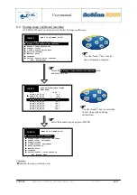
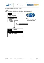
Страница 40: ...ys to navigate the ACTEON menu CONFIG WHAT DO YOU WANT TO DO Averaging sensor response Sludge slope coefficient reminder Sensor offset adjustment Graphic screen 4 20mA outputs adjustment Relay adjustment Measure units Language Factory default value reminder ESC Escape menu Select the menu and press ENTER CONF 20 30 C 24 hrs 2 91 MEASURE g l Mode1 R1 R2 ACTEON 2050 20 Turbidimeter g l 1 3 ...

Страница 41: ...ENTER Use the and keys to increase and decrease the averaging Select the averaging desired and press ENTER CONFIG AVERAGING SENSOR RESPONSE 1 Instantaneous answer 100 Answer very strongly averaged Average on 10 measures Esc Cancel the procedure Enter Validate the averaging CONFIG WHAT DO YOU WANT TO DO Averaging sensor response Sludge slope coefficient reminder Sensor offset adjustment Graphic scr...

Страница 42: ...REMINDER CONFIG WHAT DO YOU WANT TO DO Averaging sensor response Sludge slope coefficient reminder Sensor offset adjustment Graphic screen 4 20mA outputs adjustment Relay adjustment Measure units Language Factory default value reminder ESC Escape menu CONFIG WHAT DO YOU WANT TO DO Averaging sensor response Sludge slope coefficient reminder Sensor offset adjustment Graphic screen 4 20mA outputs adj...

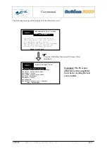
Страница 43: ...phic screen 4 20mA outputs adjustment Relay adjustment Measure units Language Factory default value reminder CONFIG EXTINCTION OF THE I R LIGHT BEAM Occult the optical slot with an opaque ruler Sensor offset 12mV DO NOT VALIDATE Extinction incomplete ESC Escape menu Enter Validate and record If the offset is too high check that the dark coloured ruler is positioned properly over the optical slot s...

Страница 44: ...ment Graphic screen 4 20mA outputs adjustment Relay adjustment Measure units Language Factory default value reminder ESC Escape menu CONFIG Cancellation of offset impossible Check the sensor the ruler might not be completely opaque and well positioned in the optical slot between the two port holes of emission and reception of the infra red beam ENTER Escape menu EXTINCTION OF THE I R LIGHT BEAM OU...

Страница 45: ...e chosen and press ENTER CONFIG Configuration of the trend curve OF THE GRAPHIC SCREEN Time base Showing maximum range 11 hours 7 minutes ESC Cancel the procedure Enter Validate the choice CONFIG WHAT DO YOU WANT TO DO Averaging sensor response Sludge slope coefficient reminder Sensor offset adjustment Graphic screen 4 20mA outputs adjustment Relay adjustment Measure units Language Factory default...

Страница 46: ...d keys to select the configuration required Select the 4 20mA output adjustment menu and press ENTER CONFIG 4 20mA OUTPUTS 4 20mA output adjustment 4 20mA output calibration CONFIG WHAT DO YOU WANT TO DO Averaging sensor response Sludge slope coefficient reminder Sensor offset adjustment Graphic screen 4 20mA outputs adjustment Relay adjustment Measure units Language Factory default value reminder...

Страница 47: ... to select 4mA or 20mA CONFIG 4 20mA OUTPUTS 4 20mA output adjustment 4 20mA output calibration CONFIG 4 20mA OUTPUTS NUMBER 1 FOR SS 4mA adjustment 0 00g l 20mA adjustment 20 00g l Configure the SS 4 20mA output and press ENTER Use the and keys to increase and decrease the 4 and 20mA stop values Use the and keys to select 4mA or 20mA CONFIG 4 20mA OUTPUTS No 2 FOR TEMPERATURE ESC Escape menu Ente...

Страница 48: ... press ENTER Comment Both 4 20mA outputs have been configured correctly CONFIG WHAT DO YOU WANT TO DO Averaging sensor response Sludge slope coefficient reminder Sensor offset adjustment Graphic screen 4 20mA outputs adjustment Relay adjustment Measure units Language Factory default value reminder ESC Escape menu ...

Страница 49: ...ect the configuration required Select the 4 20mA output calibration menu and press ENTER CONFIG 4 20mA OUTPUTS 4 20mA output adjustment 4 20mA output calibration CONFIG PROCEDURE Insert an ammeter between your device surveillance datalogger etc and the ACTEON 4 20mA outputs and press ENTER ESC Escape menu Enter To continue Insert an ammeter between ACTEON 2000 4 20mA output and your device des sor...

Страница 50: ...ust the 20mA outputs and press ENTER CONFIG WHAT DO YOU WANT TO DO Averaging sensor response Sludge slope coefficient reminder Sensor offset adjustment Graphic screen 4 20mA outputs adjustment Relay adjustment Measure units Language Factory default value reminder ESC Escape menu Use the and keys to increase and decrease the 4mA value Use the and keys to select the pH 4 20mA output or the temperatu...

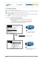
Страница 51: ...lay hunting Triggering direction Above Means the relay contact is closed above the alarm threshold Below Means the relay contact is open below the alarm threshold Forced start up and shutdown delay only in mode 3 alarme Use the and keys to select the configuration required Select the Relay adjustment menu and press ENTER Use the and keys to select the configuration required CONFIG Configuration of...

Страница 52: ...shold R1 is on Rel 2 connected to temperature measurement Alarm threshold 20 01 C Hyst 0 06 C Above the threshold R2 is on ESC Cancel the procedure Enter Validate the choice CONFIG WHAT DO YOU WANT TO DO Averaging sensor response Sludge slope coefficient reminder Sensor offset adjustment Graphic screen 4 20mA outputs adjustment Relay adjustment Measure units Language Factory default value reminder...

Страница 53: ...the threshold R1 is on Rel 2 connected to SS measurement Alarm threshold 4 51g l Hyst 0 10g l Above the threshold R2 is on ESC Cancel the procedure Enter Validate the choice Comment Both relays are configured correctly in mode 2 CONFIG WHAT DO YOU WANT TO DO Averaging sensor response Sludge slope coefficient reminder Sensor offset adjustment Graphic screen 4 20mA outputs adjustment Relay adjustmen...

Страница 54: ... Forced shutdown delay 3 min Use the and keys to increase and decrease the values Use the and keys to navigate the selections CONFIG MODE 3 ADJUSTMENT OF THE THRESHOLD HYSTERESIS AND TEMPERATURE ESC Cancel the procedure Enter Validate the choice Rel 2 connected tO temperature measurement Alarm threshold 20 01 C Hyst 0 06 C Above the threshold R2 is on Configure relay 2 and press ENTER CONFIG WHAT ...

Страница 55: ...forced shutdown delay the relay remains open regardless of the measured SS value During forced start up delay the relay remains open regardless of the measured SS value 1 50 R1 0 50 SS g l The SS value must go beyond the high threshold for at least 45 sec Forced start up delay 10 min The SS value must go beyond the low threshold for at least 45 sec 3 min Inactive Inactive Active Active 1 1 2 2 3 3...

Страница 56: ...he unit desired CONFIG CONFIG WHAT DO YOU WANT TO DO Averaging sensor response Graphic screen 4 20mA outputs adjustment Relay adjustment Measure units Languages Factory default value reminder OF UNITS ESC Cancel the procedure Enter Validate the choice Temperature C degree Celsius F degree Fahrenheit Select the required measurement unit and press ENTER CONFIG WHAT DO YOU WANT TO DO Graphic screen 4...

Страница 57: ...uage required CONFIG CONFIG WHAT DO YOU WANT TO DO Averaging sensor response Graphic screen 4 20mA outputs adjustment Relay adjustment Measure units Languages Factory default value reminder OF THE LANGUAGE ESC Cancel the procedure Enter Validate the choice Select the language French English Configure the language and press ENTER CONFIG WHAT DO YOU WANT TO DO Graphic screen 4 20mA outputs adjustmen...

Страница 58: ...procedure confirmation CONFIG CONFIG WHAT DO YOU WANT TO DO Averaging sensor response Graphic screen 4 20mA outputs adjustment Relay adjustment Measure units Languages Factory default value reminder DEFAULT VALUE REMINDER ESC Cancel the procedure Enter Validate the choice ATTENTION you will loose all your personal adjustments Yes No CONFIG WHAT DO YOU WANT TO DO Graphic screen 4 20mA outputs adjus...

Страница 59: ...output The 4mA stop is set to 5 C and the 20mA stop is set to 35 C Relay output adjustment The relays are configured in mode 1 R1 threshold 0 00g l hyst 0 20 below the threshold relay R1 is active R2 threshold 50 00 C hysteresis 0 10 above the threshold relay R2 is active Temperature measurement unit C Language English 10 Information menu The INFO window provides information on the device type and...

Страница 60: ...ure 25 C to 55 C Power supply 230 115VAC 60Hz optional 12 24VDC Protected by a 250mA fuse Max power consumption 10VA 4 20mA outputs 2 galvanic isolation outputs max resistive load 700ohms Adjustable from 0 00 to 20 00g l or 0 00 to 50 00g l depending on the model Adjustable from 10 00 C to 50 00 C Relay outputs 2 relays that can be configured in 3 different modes Adjustment in alarm mode 1 SS and ...

Страница 61: ...1kg Working range 0 20g l for Acteon 2050 20 0 50g l for Acteon 2050 50 Average for urban sludge in real extended aeration Emission reception wavelength λ0 950nm 5mm optical length Type of emission Pulsed Recurrence frequency 10Hz Transmitted signal intensity of light transmitted at 0 demodulated continuous low impedance 0 1V signal Unaffected by daylight NTC thermistor temperature compensation fr...

Страница 62: ...m for 1 hour in clean water surface active agent diluted scale inhibitor for dry dirt layer and limestone deposits solution Advice For better cleaning results finish cleaning by rubbing both windows with alcohol soaked cotton buds Recommended cleaning frequency For urban wastewater treatment active sludge it is recommended to clean the optics every two weeks Comment The best possible cleaning freq...

Страница 63: ...l sensor with DELRIN shaft Working temperature 20 to 55 C Pressure 5 bars max Cable stranded Measurement principle PT100 3 wire assembly 13 2 1 Maintenance Rinse the temperature sensor with a water jet every 3 months 13 2 2 Mechanical diagram 316 stainless steel tube Ø3 Ø20 5 2 O ring seals 40 8 16 61 85 ...

Страница 64: ...re displayed on the LCD screen RESET the microcontroller and follow the instructions below to reinitialise the LCD screen 1 Open the ACTEON 2050 transmitter box 2 Insert a LEAD or PLASTIC PENCIL in the hole located on the upper part of the box DO NOT USE SCREWDRIVERS OR METAL INSTRUMENTS Figure 8 Resetting ACTEON 2050 3 Check that the display screen restarts Comment Your settings and calibrations ...

Страница 65: ... PONSEL Référence NOTICE_ACTEON_2050_v001 V 002 65 67 14 2 SS measurement troubleshooting If you notice a lot of damping in the measurements Clean the SS sensor especially the optics Zero calibrate in clean water ...

Страница 66: ...yout If the temperature sensor is not connected terminal points 28 and 29 must be connected to the shunt supplied with the terminal If the temperature sensor is connected the shunt between terminal points 28 and 29 must be removed Before shutting the ACTEON cover check that the cover sealing joint is correctly positioned in its groove Relays SS turbidity Temp ...

Страница 67: ...anual PONSEL Référence NOTICE_ACTEON_2050_v001 V 002 67 67 After sales service PONSEL Service SAV 427 route de Caudan ZI de Kergoussel 56850 Caudan TEL 33 0 2 97 89 25 31 FAX 33 0 2 97 76 55 72 Serial number ...

Отзывы: