Pompetravaini SA Series Скачать руководство пользователя страница 46

Operating manual liquid ring vacuum pumps and compressors series TRH - TRS - TRM - TRV - SA & Systems type HYDROSYS - OILSYS 

46 

21.1 

– LIFTING AND MOVING OF OILSYS SYSTEMS 


DANGER! 
Danger due to overturning or crushing. The Oilsys systems must ALWAYS be handled and lifted and moved 
in horizontal position and without any oil in the tank. 
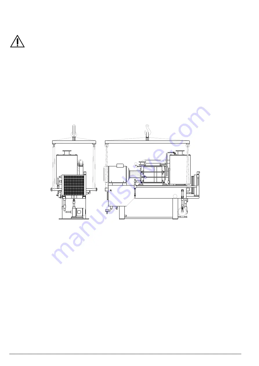
For a safe lifting it is necessary use only ropes or belts positioned on metal bars that were previously inserted 
in the lifting holes present on the base (see fig. 48) and handle it carefully to avoid damages to the system or 
harm to the operators. 
The  bars  diameter  MUST  NOT  BE  MORE  than  5  mm  smaller  than  the  diameter  of  the  lifting  holes  on  the 
base. 
During handling always use appropriate protective devices. 

 
The bars diameter must not be more than 5 mm smaller than the diameter of the lifting holes on the base. 
The lifting bars, after having been inserted in the lifting holes, must be blocked at both ends to avoid the withdraw of the 
rope or of the bars itself. 
For the lifting with ropes or belts use only a balance beam to have a traction upright to the ground. 
 
NOTE: 

The eyebolts intended for the lifting of a single component of the system MUST NOT be used to lift the entire 
pump system. 

 
For further information and clarifications ask our Sales Office. 


Fig. 48 


Содержание SA Series

Страница 1: ... NA4 IS VUOT GB00 Rev 5 5_02 2020 OPERATING MANUAL LIQUID RING VACUUM PUMPS AND COMPRESSORS Series TRH TRS TRM TRV SA Systems type HYDROSYS OILSYS ...

Страница 2: ... provided with a nameplate indicating the ATEX stamp it strictly forbidden proceed to start up the pumps but necessary to consult POMPETRAVAINI for clarifications For pumps subjected to the ATEX 2014 34 EU directive it is available a dedicated integrative manual According to what expected from 2012 19 UE Directive on Waste Electric and Electronic Equipment the electrical pump assembly from us supp...

Страница 3: ... 10 Check list prior to start up 11 Starting operating and stopping procedures 11 1 Start up 11 2 Operation 11 3 Shut down 11 4 Start up of OILSYS systems 11 5 Operation of OILSYS systems 11 6 Shut down of OILSYS systems 12 Operating maintenance 12 1 OILSYS systems 13 Bearings maintenance 14 Packed stuffing boxes 15 Mechanical seals 16 Trouble shooting problems causes and solutions 17 Repairing an...

Страница 4: ... technical information and or ordering spare parts The user is responsible for the verification of the ambient conditions where the pump will be stored or installed Extreme low or high temperatures may severely damage the pump or system unless proper precautions are taken POMPETRAVAINI does not guarantee repairs or alterations done by user or other unauthorised personnel Special designs and constr...

Страница 5: ...or pump surface Release of powder and fumes in case of rework flammable Liquid compound Gasket between flat surfaces Skin eye and breathing organs irritation Protective liquid Pump inside surface Skin and eye rash 3 IN CASE OF EMERGENCY Should the pump break down leak gas and or service liquid immediately disconnect the electrical power following the instructions given in chapter 11 Alert the main...

Страница 6: ...act POMPETRAVAINI for doubts particular conditions or in case different materials are used 4 3 PUMP MODELS AND TABLES FOR MATERIAL OF CONSTRUCTION On the pump nameplate are printed the pump serial number the year of manufacture and the pump model Refer to the following example for understanding the coding of the pump model Every letter or number in the pump model designation has a specific meaning...

Страница 7: ... pump will be stored as foreseen in our Operating Manuals we recommend a proper care to avoid oil dropping on the ground The pump or assembly must ALWAYS be moved and transported in the horizontal position Prior to moving the unit find the following total weight centre of gravity maximum outside dimensions lifting points location DANGER Danger due to overturning or crushing For safe lifting to pre...

Страница 8: ...Operating manual liquid ring vacuum pumps and compressors series TRH TRS TRM TRV SA Systems type HYDROSYS OILSYS 8 For the Oilsys systems see chapter 21 OK NO Fig 2 Fig 4 Fig 1 Fig 3 90 ...

Страница 9: ... months to avoid possible rust build up or seizing keep the pump in a dry and clean place not subjected to vibrations caused by other sources pump accessories should be subjected to similar procedure 7 INSTALLATION INSTRUCTIONS CAUTION Avoid installing the unit in narrow areas and lacking of ventilation where unfavourable conditions for the personnel may take place Allow the personnel a good visib...

Страница 10: ...ger than the pump connection size To avoid back pressure and possibility of flooding the pump when it stops it is recommended to limit the rise of the discharge piping to approximately 50 cm above the pump discharge flange Upon completion piping and connections should be tested for leakage under vacuum 7 2 ACCESSORIES Listed below are common accessories that may be supplied with the pump or added ...

Страница 11: ... approximately at the pump shaft centreline Schematic fig 6 illustrates the once through system 7 3 2 Service liquid Partial recovery system This type of installation is used where it is desired to minimise the use of fresh service liquid for calculations see chapter 19 The service liquid enters and leaves the pump same as the once through system however part of the liquid is recycled from the dis...

Страница 12: ... total recovery of service liquid depending upon the application see chapter 7 3 or 7 4 It is important to properly engineer the connecting piping to the system suction and discharge cooling lines flushing lines and draining lines The used heat exchanger is designed with service liquid being cooled approximately 4 to 6 C over the available cooling media temperature The cooling liquid flow is appro...

Страница 13: ...20 TRH 80 750 3 00 2 40 1 60 TRS 125 1550 9 90 4 50 TRH 100 870 7 40 5 70 3 80 TRS 200 1950 18 00 11 40 TRH 100 1260 TRS 200 2500 20 10 11 70 TRH 100 1600 TRS 200 3100 25 80 17 40 TRH 150 2000 12 00 9 60 6 00 TRH 150 2600 13 20 11 10 6 60 TRH 150 3100 16 20 14 10 8 70 PUMP MODEL SUCTION PRESSURE in mbar 33 200 200 600 600 TRM 25 30 0 24 0 18 0 12 TRMX TRVX 257 0 30 0 23 TRM 32 50 0 48 0 24 0 15 TR...

Страница 14: ...quid ring vacuum pump 5 Solenoid valve 6 Electric motor 7 Level gauge glass 8 Float valve 9 Heat exchanger 10 Make up solenoid valve 11 Drain valve 13 Flow control valve 13A By pass valve 14 Compound gauge 15 Level switch 16 Filter y strainer 18 Automatic drain valve check valve 4 25 27 13 22 11 26 9 14 13A 32 38 27 21 11 1 15 8 28 10 7 24 18 6 19 2 20 13 38 3 16 5 1 27 28 24 14 27 4 7 18 21 19 6 ...

Страница 15: ...f valve 24 Overflow valve 25 Draining solenoid valve 26 Solenoid valve for heat exchanger cooling liquid 27 Temperature gauge 28 Fill up connection 32 By pass piping 38 Orifice flow 48 Automatic drain valve or water trap Air or Gas Liquid Gas mixture Liquid Fig 9 Fig 10 Fig 11 4 25 27 13 22 11 26 9 14 13A 32 38 21 27 11 1 14 8 15 48 28 10 2 23 7 24 18 6 19 2 20 38 13 5 16 3 1 27 28 48 14 2 4 27 7 ...

Страница 16: ...1 8 9 4 V 7 S TRHE 32 4 7 6 2 1 OPPOSTO COMANDO LATO COMANDO COLLETTORE Z S A V TRMX TRVX 257 A TRMX 327 400 S S A V D TRMB 32 TRMB TRVB 40 50 TRVX 650 1000 1250 Z Z IN A LIQUID SERVICE D S Z V A Sul lato opposto Sul lato opposto TRVN 40 TRVN 65 TRVN 80 Z Z Z S S V V V S S S Z V D Z A A S S TRVA 65 VISTA LATO COMANDO COLLETTORI TRVA 65 V S V A D Z MANIFOLD SEEN FROM DRIVE END SEEN FROM NON DRIVE E...

Страница 17: ... 8 G 1 4 TRMX TRVX 257 TRMB 32 75 G 1 1 2 G 3 8 TRMX 327 G 1 1 4 TRMB TRVB 40 40 G 1 2 G 1 4 G 1 4 G 1 2 TRMX TRVX 400 G 1 1 2 G 1 4 TRMB TRVB 50 DN 50 G 1 8 G 3 4 G 3 4 TRVA 65 DN 65 G 1 2 G 1 2 2 TRVX 650 G 1 2 G 3 4 TRVX 1000 DN 100 G 1 G 1 2 G 1 TRVX 1250 DN 125 n 2 x G 1 4 G 1 1 2 G 1 1 2 TRVN 40 DN 40 Rp 1 4 G 3 8 G 3 8 TRVN 65 DN 65 G 3 8 G 1 2 G 1 2 TRVN 65 Z2 NPT 1 2 DN 25 1 TRVN 80 DN 80...

Страница 18: ... gauge vacuum meter and pressure gauge Z Connection for service liquid All drawings are general and schematics for additional details see the specific pump catalogue Fig 16 Pump series TRH TRS TRVA 65 with Cartridge Machanical seals costruction Fig 17 Pump series TRH TRS TRVA 65 with Double Tandem or Double Back to Back Mechanical seals flushed by reservoir construction E Mechanical seals flushing...

Страница 19: ... 100 1260 485 652 37 45 250 M 280 S TRHE 100 1600 518 690 45 75 280 S 315 S TRHA 150 2000 83 99 V2 1330 1805 740 890 75 90 315 MA 315 MB TRHA 150 2600 84 99 1480 2095 90 110 315 MB 355 S TRHA 150 3100 1630 2245 110 160 355 S 355 MB PUMP MODEL Noise level L p L W Vibration Level Weight Bare pump Weight ass ly Monoblock B5 design Weight ass ly with baseplate Operating speed RPM Installed Motor size ...

Страница 20: ...110 68 79 62 1450 1750 3 4 100 L 112 M TRVX 403 60 TRVB 40 150 69 80 64 4 5 5 112 M 132 S TRVX 405 73 TRVB 40 200 72 85 78 5 5 7 5 132 S 132 M TRVX 407 88 TRVB 50 300 88 7 5 11 132 M 160 M TRVA 65 300 70 84 133 155 161 TRVX 653 97 116 151 TRVA 65 450 146 176 201 11 15 160 M 160 L TRVX 657 115 136 170 TRVX 1003 76 89 148 173 212 15 22 160 L 180 L TRVX 1005 161 195 225 18 5 30 180 M 200 L TRVX 1007 ...

Страница 21: ...olerance 10 The assemblies Monoblock and with Baseplate are suitable for 50 Hz motors except where otherwise noted Indicated total weights for the assemblies are without motors The installed motor size cover the whole performance curve when operating as vacuum pump The electric motors over the frame size 315 M are not unified For exact weights refer to the specific motor manufacturer data In order...

Страница 22: ...4 72 66 74 69 77 77 85 11 63 71 64 72 68 78 74 82 66 75 66 74 71 79 77 86 15 65 73 64 72 68 78 74 82 67 77 69 78 71 79 78 86 18 5 67 75 66 74 68 78 74 82 70 81 71 81 72 81 78 86 22 67 75 66 74 68 78 74 82 70 81 71 81 72 81 76 85 30 69 80 68 78 73 84 82 93 70 81 72 83 72 82 78 88 37 67 75 70 81 75 86 82 93 62 74 72 83 75 86 78 88 45 67 77 72 84 75 86 82 93 62 74 67 79 75 86 80 90 55 67 77 72 84 78 ...

Страница 23: ...onsult POMPETRAVAINI for possible information 8 2 ALIGNMENT PROCEDURES FOR MONOBLOCK AND FOR PUMP MOTOR ASSEMBLY ON BASEPLATE The pump motor assembly is properly aligned by POMPETRAVAINI prior to shipment It is however required to verify the alignment prior to the start up Misalignment can occur during handling transportation grouting of assembly etc For alignment procedures of MONOBLOCK design se...

Страница 24: ...ig 20 PREPARING TO ASSEMBLE THE MONOBLOCK DESIGN COUPLING GUARD FLEXIBLE COUPLING Fig 21 CHECKING THE ALIGNMENT ON MONOBLOCK DESIGN 3 Applying slight hand pressure to the coupling guard rotate it so that one opening of the lantern is accessible see fig 21 4 Rotate by hand the coupling through the lateral opening of the lantern to make sure the pump is free 5 With a feeler gauge check the distance ...

Страница 25: ...les clean and mount pump and or motor in place and lightly tighten the bolts see fig 24 BOLTS MOTOR MOUNTING PUMP MOUNTING BOLTS Fig 24 9 With a straight edge ruler check the parallelism of the two coupling halves at several points 90 from each other see fig 26 NOTE Easier and more accurate readings can be attained with instruments such as Dial Indicators if readily available SET SCREW HALF COUPLI...

Страница 26: ...trical switch near the pump for emergency situations FOLLOW ALL SAFETY PRECAUTIONS AS LISTED IN CHAPTER 2 BEFORE DOING ANY WORK TO THE INSTALLATION DISCONNECT ALL POWER SUPPLIES All electric motors and possible connected accessories must be protected against overloading by means of circuit breakers and or fuses Circuit breakers and fuses must be sized in accordance with the full load amperage appe...

Страница 27: ...ee with the above procedures fill up the pump with a suitable solvent or lubricating liquid let it rest for several hours to allow softening of the rust build up inside the pump drain the pump and apply torque to the pump shaft as described above to finally free the rotor The selected solvent or lubricating fluid must be compatible with the pump seals and gasketing materials New pumps from the fac...

Страница 28: ... amperage than shown on its nameplate the pump motor assembly does not have abnormal vibrations and noises such as cavitation there are no leaks from mechanical seals joints and flushing or cooling liquid lines liquid level in separator is between the minimum and the maximum the operating temperature at full load does not exceed approximately 85 C CAUTION Never run the pump dry CAUTION Possible co...

Страница 29: ...t will be required to change the filter element If the gas discharge is not open to the immediate atmosphere but it is piped to other locations the pump discharge should be checked for back pressures that could cause higher power consumption and loss of pump capacity 11 6 SHUT DOWN OF OILSYS SYSTEMS Close if applicable the cooling water to the water oil heat exchanger ITEM 9 then turn off the powe...

Страница 30: ...e kept well cleaned of all mineral deposits for an effective thermodynamic heat exchange During operation a closed loop system will loose some of the service liquid due to evaporation and or saturation of the discharged gases It will be required to periodically make up fresh liquid into the system This operation is not required for those systems that are fitted with a float type automatic make up ...

Страница 31: ...Possible contact with high temperature surfaces wait for the pump cooling Maintenance must be absolutely carried out when the pump is at a standstill disconnecting the power supply and any other connection Please make sure that the power supply is restored only by the operator making the maintenance It is necessary the presence of at least two operators and a foreman must be aware there is a maint...

Страница 32: ... crushing or abrasions Possible contact with hazardous fluids cold or warm Wait for the complete pump stopping before handling the unit If the pump still contains some fluid it may suddenly start to rotate once again Take precautionary measures by draining the pump or closing the pipes by mean of a valve Remove protections only in case of maintenance Operate only provided with apposite protective ...

Страница 33: ...oper liquid circulation is done while pump is in service the piping at seal housing connection should be colder by 3 to 5 C than the outlet tubing exiting the seal housing going to the tank If this is not the case simply change the tubing on the seal housing connect tubing from inlet to the outlet and vice versa do not change the connections on the tank Sometimes this adjustment is required becaus...

Страница 34: ...h the mechanical seals MECHANICAL SEALS WITH QUENCH There are two types of Quench Barrier available upon request API Plan 61 and 62 System Plan 61 see fig 35 includes a bushing on the back of the seal at atmospheric pressure side single or double to hold the bulk of the liquid in the event of accidental failures The bushing requires a minimum clearance over the shaft therefore the liquid is NOT se...

Страница 35: ... liquid from an outside source API Plan 52 Fig 35 Example of SINGLE mechanical seal with QUENCH API Plan 01 61 NOTE Continuous flushing is not possible Fig 36 Example of SINGLE mechanical seal with QUENCH API Plan 01 62 Drenaggio Sfiato Bussola di sicurezza senza contatto Pressione max superiore di 0 3 bar alla pressione atmosferica Tenuta a labbro strisciante Pump working pressure Max pressure 0 ...

Страница 36: ...ow lit min for single seals or double in series type seals tolerance 25 depending upon temperatures NOTE DOUBLE quantity of liquid flow for double mechanical seals back to back type CAUTION Flushing liquid PRESSURE for back to back double seals must be min 0 5 bar over the max pump working pressure while NOT more than 0 3 bar over the atmospheric pressure in case of double seals in series TANDEM 1...

Страница 37: ...VB 40 110 150 2 6208 2RSR TRMB 40 200 50 300 1 1 3210 2RSR 6308 2RSR 45 TRVB 40 200 50 300 1 1 6210 2RSR 6208 2RSR TRMX 403 405 2 6306 2ZC3 TRMX 407 6308 2ZC3 55 TRVX 403 405 6208 2Z 45 TRVX 407 1 1 6208 2Z 6210 2Z 55 TRHC TRSC 40 TRHE 40 140 190 TRSC TRSE 50 2 6306 2RSR 2 35 TRHB 50 TRVA 50 e 65 6308 60 43 TRHB C 80 TRSB C 100 6310 90 55 TRVX 650 1 1 6308 3207B 45 TRVX 1000 1 1 3210 6310 70 55 55...

Страница 38: ...um see tab 3 8 High service liquid flow Reduce the service liquid flow adjust the by pass valve 9 High back pressure Check the discharge line for obstructions or high friction losses reduce the back pressure to maximum 0 1 bar 10 Wrong pump motor assembly Verify that the base surface is level and that all pump feet are resting on the surface add spacers if required see chapter 11 11 Mechanical sea...

Страница 39: ...n and discharge flanges remove the coupling guard remove the spacer of the coupling if there is one if required remove the motor anchor bolts on the baseplate for base mounted assembly or the bolts on the adapter flange in the case of monoblock design remove the pump anchor bolts on the baseplate remove the pump from the installation Avoid damaging other system components Before returning the pump...

Страница 40: ...eded Fig 38 Single stage pump series TRM TRS TRV CAPACITY FACTOR Fig 39 Two stage pump series TRH CAPACITY FACTOR LIMITE CAPACITA DI ASPIRAZIONE Lowest allowable suction pressure Service water temperature TEMPERATURA DELL ACQUA DI ESERCIZIO 50 C 45 C 40 C 35 C 32 C 30 C 28 C 26 C 24 C 22 C 20 C 18 C 16 C 15 C 14 C 12 C 10 C PRESSIONE ASSOLUTA Absolute pressure PRESSIONE ASSOLUTA Absolute pressure ...

Страница 41: ...nd service liquid have same temperature 19 3 OPERATION WITH PARTIAL RECOVERY OF SERVICE LIQUID Where the working conditions will allow it the service liquid temperature can be increased utilising a smaller quantity of fresh liquid from an outside source A similar flow as the make up is discharged to the drain while the balance of liquid required by the pump is recirculated In these cases the servi...

Страница 42: ...g vacuum pumps and compressors series TRH TRS TRM TRV SA Systems type HYDROSYS OILSYS 42 19 4 UNIT CONVERSION TABLE Absolute pressure Vacuum Dry air flow at 15 C Saturated vapour flow Saturated water temperature Vaporization heat ...

Страница 43: ...quid the higher the losses in pump capacity and maximum vacuum see chapter 19 This system is particular suitable where the service liquid and the condensed gases cannot be discharged to the environment either for pollution reasons or because the fluids are too valuable The PARTIAL RECOVERY system see fig 42 and legend on following page requires a constant flow of cold make up liquid from an extern...

Страница 44: ...e 25 Solenoid valve for overflow 26 Solenoid valve for cooling liquid 27 Thermometer 28 Fill connection 30 Frame 32 By pass piping 33 Connection cooling lines 34 Temperature switch 35 Vacuum relief valve 48 Automatic drain valve for systems used as Compressor only Tab 11 GENERAL AND NOT BINDING ENGINEERING DETAILS FOR HYDROSYS OILSYS SYSTEMS PACKAGE SERIES Motor size Dry weight without Pump and Mo...

Страница 45: ...cuum pumps there are no moving parts that come in contact with each other therefore there is no need for lubrication of the pump internals these are very robust and reliable pump packages which offer extended operating life even when handling condensable gases See tab 13 for materials of construction and tab 11 in chapter 20 for some engineering data COMPONENT MATERIAL DESIGN Vacuum pump GH F RA F...

Страница 46: ...m or harm to the operators The bars diameter MUST NOT BE MORE than 5 mm smaller than the diameter of the lifting holes on the base During handling always use appropriate protective devices The bars diameter must not be more than 5 mm smaller than the diameter of the lifting holes on the base The lifting bars after having been inserted in the lifting holes must be blocked at both ends to avoid the ...

Страница 47: ...Operating manual liquid ring vacuum pumps and compressors series TRH TRS TRM TRV SA Systems type HYDROSYS OILSYS 47 ...

Страница 48: ...rettiva Macchine Machinery Directive 2006 42 CE Compatibilità elettromagnetica EMC Directive 2014 30 UE I Questa dichiarazione perde validità nel caso in cui alla macchina venissero apportate delle modifiche non esplicitamente approvate dal costruttore o nel caso di un uso non conforme della macchina GB This certificate will be invalidated in case any modification not approved by the manufacturer ...

Отзывы: