


Operating manual liquid ring vacuum pumps and compressors series TRH - TRS - TRM - TRV - SA & Systems type HYDROSYS - OILSYS
41
19.2 - SERVICE LIQUID TEMPERATURE CHANGE ACROSS THE PUMP
The service liquid of a liquid ring pump absorbs total heat Q
T
as follows:
Q
T
(kJ/h) = Q
c
+ Q
K
+ Q
R
Where:
Q
C
= 0,9 x
P x 3600 = Isothermal compression heat
Q
K
= m
V
x r
= Condensation heat
Q
R
= m
g
x c
p
x
T
a
= Cooling heat (Generally negligible, ignored in calculation of Q
T
)
m
v
= mass condensed incoming vapour in kg/h
m
g
= mass incoming gas in kg/h
P
= absorbed power at operating point in kW
c
P
= gas specific heat in kJ/Kg x K
r
= heat of vaporisation in kJ/Kg
T
a
= differential temperature in K, between incoming gas T
G
and service liquid discharge temperature (T
2
+
T)
K
= Kelvin temperature
Once the Q
T
is known it is possible to calculate the differential temperature
T of the pump service liquid:
T
Q
Q
c
T
A
p
Where:
Q
T
= total heat load before calculated in kJ/h
Q
A
= pump service liquid flow in m
3
/h
= service liquid density in kg/m
3
(water = 1000)
c
P
= service liquid specific heat in kJ/kg x K
(Some values for c
P
: Water = 4,2 - Air = 1,0 - Water Vapour = 1,84)
NOTE: It can be assumed that the discharge gas and service liquid have same temperature.
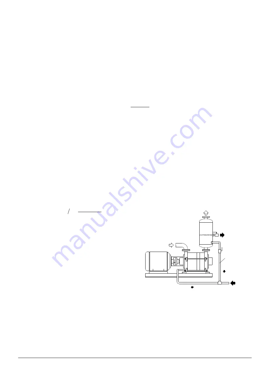
19.3 - OPERATION WITH PARTIAL RECOVERY OF SERVICE LIQUID
Where the working conditions will allow it, the service liquid temperature can be increased utilising a smaller quantity of
fresh liquid from an outside source. A similar flow as the make-up is discharged to the drain while the balance of liquid
required by the pump is recirculated. In these cases the service liquid working temperature rises and the pump capacity
will require correction per curves of fig. 38 and 39. The system installation will be similar to the schematic of fig. 40.
Depending upon the affordable loss of capacity the service liquid temperature T
2
may be set and the make-up flow of
fresh liquid Q
F
can then be calculated:
Q m h
Q
T
T
T
T
F
A
3
2
1
where:
Q
F
= Fresh make-up flow from outside source in m
3
/h
Q
A
= Total service liquid flow required for the operating
conditions in m
3
/h
T
= Service liquid temperature rise (see chapter 19.2)
T
2
= Service liquid temperature to pump
T
1
= Temperature of make-up liquid
The fig. 40 indicates a generic schematic of a liquid ring
vacuum pump in a partial recovery system.
By closing the recirculation line the system would become a
“once through” installation where all the service liquid is
drained, therefore:
Q
A
= Q
F
and
T
2
= T
1
kW
Q
F
Q
F
,T
1
Q
A
,T
2
Q
A
-Q
F
T
2
+
T
~T
2
+
T
Recirculation
line
T
G
Fig. 40