


Operation
42
Atlas
®
Digital Amplifier Complete Technical Reference
4
4.4
Commutation
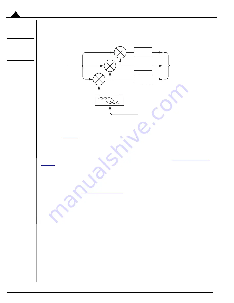
Figure 4-3:
Commutation
Control
Sequence
Brushless DC motors have three phases (generally referred to as A, B, and C) separated from each other by 120
electrical degrees. The process of splitting up the overall torque command into constituent phase commands is called
commutation.
provides an overview of the control sequence when a brushless DC motor is controlled by
Atlas.
The first step is that the external controller specifies the desired motor voltage or torque command to the Atlas. This
command is then commutated into constituent phase-specific values. This process applies to step motors as well as
Brushless DC motors, however for step motors the process is called microstepping. See
for a detailed discussion of step motor control with Atlas amplifiers. DC Brush motors are single phase
devices, and do not require commutation.
Once commutated, the individual commands for the A, B, and C phases are output either directly to the power stage
or to the current loop module (depending on whether current control has been requested). If output to the current
loop module, additional calculations are performed using the measured current through each winding to determine a
final phase command. See
4.4.1
Determining Phase Angle
Atlas does not directly accept commutation inputs such as Hall sensors, so phase angle information must be provided
by the external controller via the SPI interface.
Phase angle in this context means the position of the motor within its overall electrical cycle. Whether or not the
electrical phase angle corresponds directly to the mechanical motor angle depends on how many poles the motor has.
The most common brushless DC motor configuration has four poles (two pole pairs), meaning it traverses two full
electrical cycles for each rotation of the motor. In this example therefore, the mechanical angle would be half of the
electrical angle.
The phase angle that is provided to Atlas by the external controller is encoded as a 12 bit word, consisting of the
instantaneous electrical angle of the rotor. A minimum angle of 0 corresponding to an electrical phase angle of 0.0
°
,
and a maximum value of 4,095 corresponding to a value of 359.9
°
. Phase angles expressed to Atlas are always positive
and have a maximum value of 360.0
°
. This means a motor that moves in the negative direction from a position angle
Motor Output
(PWM or DAC)
SPI Voltage
or
Torque Command
Phase
Angle
To
current
loop or
power
stage
Phase A
Command
Phase B
Command
Phase C
Command


