


Electrical Specifications
Atlas
®
Digital Amplifier Complete Technical Reference
35
3
3.9.3
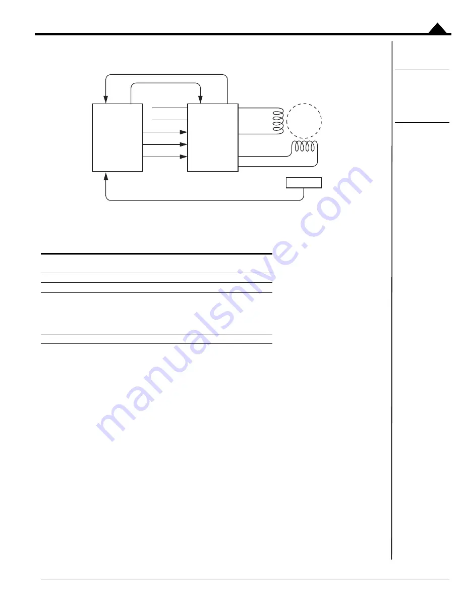
Step Motors in Pulse & Direction Signal Mode
Figure 3-10:
Step Motor
Pulse and
Direction Mode
Connections
The following table summarizes the recommended connections when connecting Atlas amplifiers to two-phase step
motors when using the pulse & direction signal mode. In this mode the external controller provides position
commands to Atlas via pulse and direction signals.
These connections apply to bipolar motors. If connecting to unipolar motors do not connect the center tap.
In this configuration the external controller generally consists of an off-the-shelf motion control card or module, a
programmable microprocessor or DSP-type device, or a FPGA (field programmable gate array). The external
controller provides a continuous stream of pulse and direction commands, along with (optionally) an
AtRest
signal to
control the torque.
To initially set up and store its application-specific configuration parameters, Atlas is programmed using the SPI
interface and then commanded to convert to pulse & direction signal mode.
FaultOut
signal input to external controller is strongly recommended when the Atlas is used in Pulse & Direction signal
mode.
Type
Required Connections
Optional
Connections
Power
HV, Pwr_Gnd
Communication
Pulse, Direction, GND
AtRest
Motor, Phase A
+
:
Motor, Phase A
-
Motor, Phase B
+
:
Motor, Phase B
-
:
Motor A
Motor B
Motor C
Motor D
Miscellaneous
~Enable
FaultOut
Enable
Pwr_Gnd
FaultOut
Optional Encoder Feedback
Encoder
Atlas
®
Digital
Amplifier
2 - Phase
Step
Motor
External
Controller
Pulse
Direction
AtRest
Motor A
Motor B
Motor C
Motor D
HV


