background image

Using WallNet Assistant

42

Planar UltraLux Series Installation Guide

3

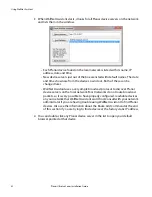
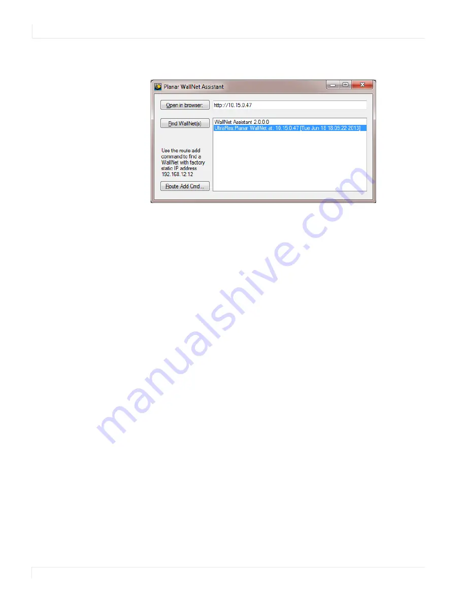
When WallNet Assistant starts, it looks for all Planar device servers on the network 
and lists them in the window.

• Each Planar device found on the local network is listed with its name, IP 

address, date and time.

• New device servers just out of the box are listed with default names. The date 

and time shown are from the device’s own clock. Both of these can be 
changed later.

• WallNet Assistant uses a very simple broadcast protocol to discover Planar 

device servers on the local network. Most networks do not route broadcast 
packets, so it is very possible to have properly configured, reachable devices 
on your network that WallNet Assistant won’t find. Consult with your network 
administrator if you are having trouble using WallNet Assistant to find Planar 
devices. Also see the information about the Route Add Command at the end 
of this section if you are trying to find a device at the factory static IP address.

4

You can double-click any Planar device server in the list to open your default 
browser pointed at that device.

Содержание UltraLux Series

Страница 1: ...Planar UltraLux Series...

Страница 2: ...ans will help you maximize your investment by providing great support display uptime and performance optimization From post sale technical support to a full suite of depot services our services are pe...

Страница 3: ...Information 13 Recommended Usage 14 Burn In Versus Temporary Image Retention 14 Normal Use Thermal Guidelines 15 Using the Display in Flat Orientation 15 Installing the Planar UltraLux Series 16 Befo...

Страница 4: ...on 31 Utility 31 Options 32 Uninstalling the MultiTouch Driver 32 External Control and Monitoring 33 RS232 Communication 34 Connecting the RS232 Cable 34 RS232 Commands 35 SNMP Monitoring 39 Sending R...

Страница 5: ...Mounts Side Views 72 70 Touch Front and Side Views 73 80 Display Dimensions Front and Side Views 74 80 Display Dimensions Rear View 75 80 Rear View Wall Mount Hangers and Service Panel Locations 76 80...

Страница 6: ...configurations the Planar UltraLux Series provides the flexibility to specify the ideal display for any environment With value added features such as interactive touch edge to edge glass front design...

Страница 7: ...4 7 visual performance with features enabling easy service and installation Caution AC power cord needs to be away from the component boxes shown here This is due to the very low profile of the space...

Страница 8: ...the display from the wall reduces complexity and service time by up to 70 Control Module On the back of the UltraLux display is a replaceable control module that contains the inputs and outputs shown...

Страница 9: ...ports Power Board This is used to generate the required voltages needed to run the control module Integrated Media Player Storage Planar UltraLux displays incorporate a 1U media player compartment ena...

Страница 10: ...l Note that only the buttons highlighted below are applicable to the UltraLux Series panels Turns on off the AC power to the LCD module Mutes the audio Press to access on screen menus Four arrow keys...

Страница 11: ...des with one wider than the other A grounding type plug has two blades and a third grounding prong The wide blade or the third prong is provided for your safety When the provided plug does not fit int...

Страница 12: ...or objects have fallen into the display or if the displays have been exposed to rain or moisture do not operate normally or have been dropped 16 Keep the packing material in case the equipment should...

Страница 13: ...verzamelpunt voor de recyclage van elektrische en elektronische apparatuur Door te garan deren dat u dit product op de correcte manier wegwerpt helpt u potenti le negatieve gevolgen voor het milieu en...

Страница 14: ...efined as displaying continuously changing video patterns or images However LCD modules can experience temporary image retention when recommended usage guidelines are not followed What is Temporary Im...

Страница 15: ...LCD module cannot be above 104 F 40 C and 35 C for 80 portrait nor below the minimum ambient operating temperature of 32 F 0 C If one of these conditions exists it is up to the installer to ensure th...

Страница 16: ...ding on the size of the display this list may be different 1 and 2 Phillips screwdriver Drill and bits Nut drivers Pencil Digital laser level Ladders lift Back brace Stud finder if hanging LCD modules...

Страница 17: ...17 Powering On Off Displays There are several ways to turn the UltraLux Series on or off Use the on off switch on the AC power inlet Use the power button on the remote control Use the RS232 commands...

Страница 18: ...will need a minimum of eight screws for the top mounting bracket and a minimum of four for the bottom kickstand bracket Additional screws may be needed depending on your installation Accessory Kit Par...

Страница 19: ...on Guide 19 Optional Planar Supplied Accessories The following optional items are available to order as part of your installation Planar ContentSmartTM Media Player ProfileTM Wall Mount IR extender ca...

Страница 20: ...ate studs to support the weight of each display if installing on a wall The UltraLux must be installed on a flat surface Use supplied UltraLux mounting template for top and bottom bracket installation...

Страница 21: ...t the display be sure that it is sufficiently engineered to handle the weight of the display Also be sure to purchase the correct hardware needed to support the display mounted to that structure 1 Fin...

Страница 22: ...n Guide 3 Use the provided template to determine the center points of the wall mounts The V notches are labeled L for a landscape display or P for a portrait display Use the appropriate V notch to ali...

Страница 23: ...g a landscape display and the template is too long you can break the template at the notch labeled P 5 Let the template hang vertically so it is plumb as the bottom hole in the template determines whe...

Страница 24: ...Tighten the screw into the mount 10 Use a level to make sure the mount is level 11 Then install additional screws as needed Note Screws installed near the mount hooks provide the best support 12 Inst...

Страница 25: ...Wall Planar UltraLux Series Installation Guide 25 13 Install the kickstand bracket to the back of the display using four M4 x 8 panhead screws Landscape holes for kickstand bracket installation Portr...

Страница 26: ...ion Guide 14 Using three strong people carefully hang the back of the display onto the top wall mount bracket using the square brackets on the back of the display Caution Be sure these are securely hu...

Страница 27: ...Planar UltraLux Series Installation Guide 27 15 On the bottom wall mount there is locking hardware in the lower corners of the mount Push the hardware up and finger tighten the captive screws on the...

Страница 28: ...ut having to remove the display from the wall Use the following instructions to put the display in service mode 1 Loosen the captive locking screws on both sides of the bottom mount 2 Pull the display...

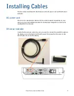
Страница 29: ...talled into the back of the control module Depending on your setup you may need additional cables for media player integration as well as for sending RS232 commands IR sensor extender In order for the...

Страница 30: ...have at least 1 clearance to connect the USB and power 2 Plug in the 5V 4A Power supply connector to the touchscreen power connector Note USB and Power connection to the touchscreen 3 Connect the 5V...

Страница 31: ...on MultiTouch Platform to open the PQLabs MultiTouch Platform window Touchscreen Information Serial Number Displays the serial number of the connected touchscreen Firmware Version Displays the firmwar...

Страница 32: ...upport Flash Tuio Support Handwriting Optimization Enable Windows Native Touch Enable Mouse Keyboard Simulation and Launch When Windows Starts Up Flexible Scan Rate is at a default setting Uninstallin...

Страница 33: ...aLux remote control and display there are other methods of controlling the UltraLux externally Using a serial RS232 link to send commands and to receive responses to those commands Using SNMP Simple N...

Страница 34: ...If your installation will not use RS232 control skip this section Most things you can do with the remote you can do with RS232 commands Plus you can send inquiries to the displays and find out the cu...

Страница 35: ...f mode backlight off 2 Set Power to on 08 22 FD 00 00 00 00 D9 video board is set to soft power on mode backlight on if video source is present or when first searching for video source 3 Get Power Sta...

Страница 36: ...color temperatures 17 Get Red 04 21 0C CF returns Red Color value 18 Set Green to X 0 to 100 Set to 20 08 22 0F 00 00 00 14 B3 green set to commanded value 19 Get Green 04 21 0D CE returns Green Colo...

Страница 37: ...r Space value 34 Do an Auto Adjust 08 22 07 00 00 00 00 CF if VGA analog source is present a sync timing auto adjust is done 35 Do Auto Color Adjust 08 22 08 00 00 00 00 CE if VGA source is present a...

Страница 38: ...ntrast or brightness settings in effect or input source is VGA 43 Set HDMI Full Range to on 08 22 19 00 00 00 01 BC sets the standard HDMI Full Range where for each color the range is 0 for black and...

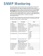
Страница 39: ...ystem or communication error and normal return values are zero or positive integers Object Name Description Value plnrModel Model name string UltraLux plnrInputSelect User selected input source 1 HDMI...

Страница 40: ...erminal program such as the Hercules SETUP utility available from www HW group com Note Ensure that the Enable ASCII command service UDP port 57 box is checked on the Access Control page of the Remote...

Страница 41: ...s the Remote Monitoring functions 1 WallNet Assistant is distributed as Planar_WallNet_Assistant_ version zip Extract all files to a new folder in your Program Files folder or another convenient locat...

Страница 42: ...Net Assistant uses a very simple broadcast protocol to discover Planar device servers on the local network Most networks do not route broadcast packets so it is very possible to have properly configur...

Страница 43: ...Using WallNet Assistant Planar UltraLux Series Installation Guide 43 5 When your browser connects to a Planar network device you should see a page similar to the following...

Страница 44: ...utton the route add command window shown above opens 2 The area circled in the example above shows the syntax of the route add command The final IP address on the command line must be the IP address o...

Страница 45: ...trol for example powering the displays on and off either manually or per a pre defined schedule Remote Monitoring Home This is the first page you will see when you open the Planar UltraLux Remote Moni...

Страница 46: ...46 Planar UltraLux Series Installation Guide Unit Status The Unit Status page shows a list of the different system settings for the LCD It also shows whether or not the two power supplies contained in...

Страница 47: ...Lux Remote Monitoring Planar UltraLux Series Installation Guide 47 Display Control The Display Control page contains two sub pages Power On Off and Custom Commands Setup These are described in the fol...

Страница 48: ...control AC power through Planar UltraLux Remote Monitoring This section has four options for which you can schedule an automatic power on off The options are no automatic power on off same daily sched...

Страница 49: ...u will see an output page showing the commands sent and replies received if any Use the browser s Back button to return from this results page to avoid losing unsaved changes If you select the Custom...

Страница 50: ...e Monitoring 50 Planar UltraLux Series Installation Guide Admin Setup The Admin Setup page contains three sub pages Network Setup Time and Date Access Control and Software Update These are described i...

Страница 51: ...te This will be the name for this particular server The hostname is limited to 16 characters alphanumeric dash or underscore only 2 If you want to enter a domain name for server name lookups type it i...

Страница 52: ...r the Network mask DNS server s and Gateway as instructed by the network administrator c Go to step 6 6 Scroll to the bottom of the page and click Confirm and apply new network settings to receive the...

Страница 53: ...the NTP server name or address and poll interval in the Date and Time Server section Click Apply new date and time server settings Note If you don t have a preferred NTP server then www pool ntp org...

Страница 54: ...oring 54 Planar UltraLux Series Installation Guide Access Control The Access Control page allows you to set parameters needed to access the web the Remote Monitoring network RS232 commands as well as...

Страница 55: ...is downloaded to a local drive 2 Click the Load Software button to load the new software This process can take a few minutes depending on the speed of the network update It is very important that you...

Страница 56: ...is link live click Change Product ID Link 7 In normal operations Remote Monitoring polls the displays at a rate of one per second to look for user requests that have been made using the IR remote cont...

Страница 57: ...Screen Display Menus On screen menus can be accessed using the remote control These menus allow you to adjust image brightness contrast sharpness color sound and various System Settings Below are pic...

Страница 58: ...On Screen Display Menus 58 Planar UltraLux Series Installation Guide Image Menu...

Страница 59: ...K 5000K 6500K 9300K 7500K user Full color Red Green Blue srgb xvycc Note Some settings are not always active and may be grayed out For instance auto is a color adjustment available only when the activ...

Страница 60: ...splay Menus 60 Planar UltraLux Series Installation Guide Display Menu Display position phase Display Auto adjust clock Move position H Move position V Note The Display Menu is active only for analog v...

Страница 61: ...UltraLux Series Installation Guide 61 Sound Menu mute Sound volume Note For Mute a caret indicates Mute is off which means sound is on A power symbol means the mute is on Use the left and right arrow...

Страница 62: ...On Screen Display Menus 62 Planar UltraLux Series Installation Guide System Menu...

Страница 63: ...Lux Series Installation Guide 63 system Input OSD Settings Display Port VGA 3 sec 6 sec 12 sec DVI HDMI Timer Rotation 0 90 180 270 Position Transparency OSD Language English Spanish German French Res...

Страница 64: ...oles Planar Profile mounting or VESA 400x400 4 holes Planar Profile mounting or VESA 600x600 4 holes Orientation Portrait Landscape Recommended Usage 24 7 Aspect Ratio 16 9 Brightness typical 700 nits...

Страница 65: ...ontal Frequency Pixel Frequency VGA 640 x 480 60 Hz 31 5 kHz 25 157 MHz SVGA 800 x 600 56 Hz 35 2 kHz 36 MHz SVGA 800 x 600 60 Hz 37 9 kHz 40 MHz XGA 1024 x 768 60 Hz 48 4 kHz 65 MHz WXGA 1280 x 720 6...

Страница 66: ...66 Planar UltraLux Series Installation Guide UltraLux Dimensions 70 Display Dimensions Front and Side Views...

Страница 67: ...70 Display Dimensions Rear View Planar UltraLux Series Installation Guide 67 70 Display Dimensions Rear View...

Страница 68: ...70 Rear View Wall Mount Hangers and Service Panel Locations 68 Planar UltraLux Series Installation Guide 70 Rear View Wall Mount Hangers and Service Panel Locations...

Страница 69: ...70 Landscape Wall Mounts Front and Bottom Views Planar UltraLux Series Installation Guide 69 70 Landscape Wall Mounts Front and Bottom Views Note Shown from the bottom of the panel...

Страница 70: ...70 Landscape Wall Mounts Side Views 70 Planar UltraLux Series Installation Guide 70 Landscape Wall Mounts Side Views...

Страница 71: ...Mounts Front View Planar UltraLux Series Installation Guide 71 70 Portrait Wall Mounts Front View Note Shown from the bottom of the panel 63 287 1 3 1 1 5 6 59 67 1 3 1 2 6 5 6 1 7 2 3 1 3 1 2 6 5 6...

Страница 72: ...unts Side Views 72 Planar UltraLux Series Installation Guide 70 Portrait Wall Mounts Side Views 63 287 1 3 1 1 5 0 1 080 67 1 5 167 0 1 080 728 167 1 Installed position Service position with kickstand...

Страница 73: ...70 Touch Front and Side Views Planar UltraLux Series Installation Guide 73 70 Touch Front and Side Views Note All other dimensions are the same as non touch 70...

Страница 74: ...80 Display Dimensions Front and Side Views 74 Planar UltraLux Series Installation Guide 80 Display Dimensions Front and Side Views...

Страница 75: ...80 Display Dimensions Rear View Planar UltraLux Series Installation Guide 75 80 Display Dimensions Rear View...

Страница 76: ...80 Rear View Wall Mount Hangers and Service Panel Locations 76 Planar UltraLux Series Installation Guide 80 Rear View Wall Mount Hangers and Service Panel Locations...

Страница 77: ...80 Landscape Wall Mounts Front and Bottom Views Planar UltraLux Series Installation Guide 77 80 Landscape Wall Mounts Front and Bottom Views...

Страница 78: ...80 Landscape Wall Mounts Side Views 78 Planar UltraLux Series Installation Guide 80 Landscape Wall Mounts Side Views...

Страница 79: ...80 Portrait Wall Mounts Front View Planar UltraLux Series Installation Guide 79 80 Portrait Wall Mounts Front View...

Страница 80: ...80 Portrait Wall Mounts Side Views 80 Planar UltraLux Series Installation Guide 80 Portrait Wall Mounts Side Views...

Страница 81: ...80 Touch Front and Side Views Planar UltraLux Series Installation Guide 81 80 Touch Front and Side Views Note All other dimensions are the same as non touch 80...

Страница 82: ...File required by this Directive is maintained at the corporate headquarters of Planar Systems Inc 1195 NW Compton Drive Beaverton OR 97006 Note This equipment has been tested and found to comply with...

Страница 83: ...Planar employees When you purchase a Planar product you get more than a display you get the service and support you need to maximize your investment To find the latest warranty and service information...

Страница 84: ...84 Planar UltraLux Series Installation Guide Accessing Planar s Technical Support Website Go to www planar com support for warranty information user manuals touch drivers and other support information...

Страница 85: ...via Remote Monitoring 47 custom commands in Remote Monitoring 49 customer support hours of operation 83 phone numbers 83 website 83 customer supplied accessories 19 D date changing in Remote Monitorin...

Страница 86: ...lation 16 portrait wall mounts front view 71 72 power on off for remote monitoring 48 supply 9 turning on off 17 preparing your installation location 17 product architecture of control module 10 R reb...

Страница 87: ...equipment list 16 U UltraLux display installing on a wall 21 UltraLux Series features 7 integrated media player 9 LED technology 9 mounting system 8 product architecture 10 remote control 10 unit sta...

Отзывы: