background image


Connecting User Devices 

1.


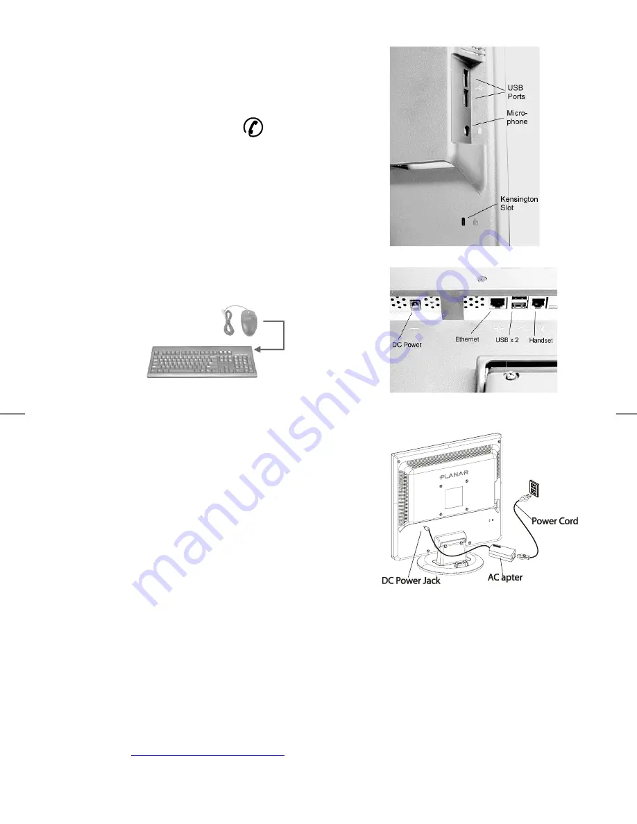
USB devices such as the Keyboard can be connected to ports on 
the side or bottom    (See Fig. 1-6 and Figure 1-7) 

2.


The unit may be secured through the use of Kensington locking 
devices. (See Figure 1-6) 

3.


The Headset/Handset port (RJ22)


is reserved for future 

use with VOIP software support tools. It is designed for 
connection to analog telephone headsets or handsets. We 
recommend only the use of a UL or other safety agency 
approved device. 
 

Caution: This is not a telephone modem connection and should 
not be connected to a telephone line. Damage to the unit might
occur. 


Figure 1-6


4.


The PS2 Mouse connects to the PS2 connector on the right end 
of the keyboard.   


5.


A stereo headphone may be connected to the front of the 
Network Display 


Figure 1-7 

 
Connecting the AC Power 


1.


Connect the power cord to the AC adapter (See Fig. 1-8)   

2.


Connect the AC adapter’s DC output connector to the DC 
Power Jack of the display.


3.


Connect the power cord to a 100-240 VAC, 50/60Hz power 
source.


Figure 1-8 

Setting Up the Network Display 

1.


Make sure the AC power cord is connected to the Power Adapter.   

2.


Press the Network Display's power switch, located on the bezel of the monitor. (See Figure 2-1) 

3.


After power-on, the thin client will boot and commence a series of tests and communication checks which 
will be shown in the System Information Event Log. 

4.


For the Network Display to properly connect to your network and applications servers, the Network Display 
and your network environment must be appropriately configured.    Please contact your Information 
Technology specialist for further details.   

5.


A detailed User Guide and Administrators Guide for the Wyse Thin Client Operating System (WTOS) may be 
obtained at 

http://www.planar.com/support/

 for this product model number. 


Содержание ND1750

Страница 1: ......

Страница 2: ......

Страница 3: ...m Its Stand 5 Interface for Arm Wall Mount Applications 5 Connecting the Display to Your Network 5 Connecting User Devices 6 Connecting the AC Power 6 Setting Up the Network Display 6 Display Controls...

Страница 4: ...encewillnot occurinaparticularinstallation Ifthisequipmentdoescauseharmfulinterferencetoradioortelevisionreception whichcanbe determinedbyturningtheequipmentoffandon theuserisencouragedtotrytocorrectt...

Страница 5: ...Network Display in a room with a room temperature of 20 60 C or 4 140 F Storing the Network Display outside this range could result in permanent damage 6 If any of the following occurs immediately unp...

Страница 6: ...r product and services register your Planar product today Visit our website to register your product at http www planar com support product_registration html Cables Replacement Lamps and Accessories T...

Страница 7: ...nd 2 1 3 version 1 dated 13 November 1997 Note M4mm x 11mm L screws should be used for a 3mm thick mounting plate application Thicker plates should use appropriately longer screws The screw threads sh...

Страница 8: ...Power 1 Connect the power cord to the AC adapter See Fig 1 8 2 Connect the AC adapter s DC output connector to the DC Power Jack of the display 3 Connect the power cord to a 100 240 VAC 50 60Hz power...

Страница 9: ...controls and indicators 5 4 1 3 2 Figure 2 1 1 Power Control LED Modes are changed by pressing the Power Control Button Please refer to Figure 2 2 2 Brightness Function Adjust increase 3 Brightness Fu...

Страница 10: ...een If the Power button is momentarily pressed when in the Off mode the display is powered and the thin client will boot If the Power button is momentarily pressed while in Standby mode the display re...

Страница 11: ...ightness 300 cd m2 typical 300 cd m2 typical Contrast Ratio 800 1 typical 800 1 typical Response Time 5ms typical 5ms typical Color Temperature 6500 K Factory Calibrated 6500 K Factory Calibrated Cont...

Страница 12: ...tive Humidity 5 C to 40 C 41 F to 104 F 20 to 80 20 C to 60 C 4 F to140 F 5 to 85 Power Supply AC Input Input Voltage Single phase 100 240VAC 50 60 Hz Input Current 1 5 A maximum Size and Weight ND175...

Страница 13: ...the Power Adapter should be green 3 Verify that the Power Indicator on the Network Display is green 4 Turn off the Network Display and then turn it back on again PROBLEM The displayed image is dim If...

Страница 14: ...this License to install and or use the Software in object code only solely in conjunction with your Planar manufactured hardware Device You have the right to use this Software by loading it onto a co...

Страница 15: ...tware is provided AS IS with all faults and with no warranties of any kind whether express implied or statutory LICENSOR SPECIFICALLY DISCLAIMS ALL WARRANTIES REPRESENTATIONS OR CONDITIONS INCLUDING B...

Страница 16: ......

Отзывы: