22
/48
Installation, use and maintenance
M0583
IN DETAIL:
1
Power supply
cable:
Power supply cable:
Insert the grounding wire (yellow/green sheath) into the central hole of
the terminal, then phase and neutral respectively on the left and right and
tighten the wire fixing screws
Voltage values:
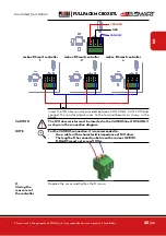
The electronic controller must be supplied with voltages and frequencies
compatible with the motor to be driven:
•
If the motor is 230 V ac 50 Hz, the controller must be supplied at the
same voltage and frequency
•
If the motor is 120 V ac 60 Hz, the controller must be supplied at the
same voltage and frequency
WARNING
The cable cross-section must be chosen according to the electrical current
absorbed by the motor, which is the device in which almost all the current
flows.
Pay attention to the cable specifications:
- SIGNAL AND POWER SUPPLY WIRING CONNECTED IN THIS BOX
MUST BE RATED AT LEAST 300V
- POWER SUPPLY AND MOTOR OUTPUT WIRING CROSS-SECTIONS
MUST BE BIGGER OR EQUAL THAN AWG16
NOTE
The maximum current that the motor can absorb is 15 A
MAIN AC/DC POWER INPUT
CN9
WE P:7.62
F/+
N/-
1
2
3
grounding
- PE -
(yellow/green)
neutral
- N -
(blue)
phase
- L-
(brown)
2
MOTOR cable:
Insert the grounding wire (yellow/green sheath) into the central hole of the
terminal, then phase and neutral respectively on the left and right and tight-
en the wire fixing screws.
On the motor terminal, when active, there are the same voltage and the
same frequency as the input from the power supply line
WARNING
The CABLE SECTION of the MOTOR must be chosen according to the
electric current absorbed by the motor


