No, IXPN E01-01E
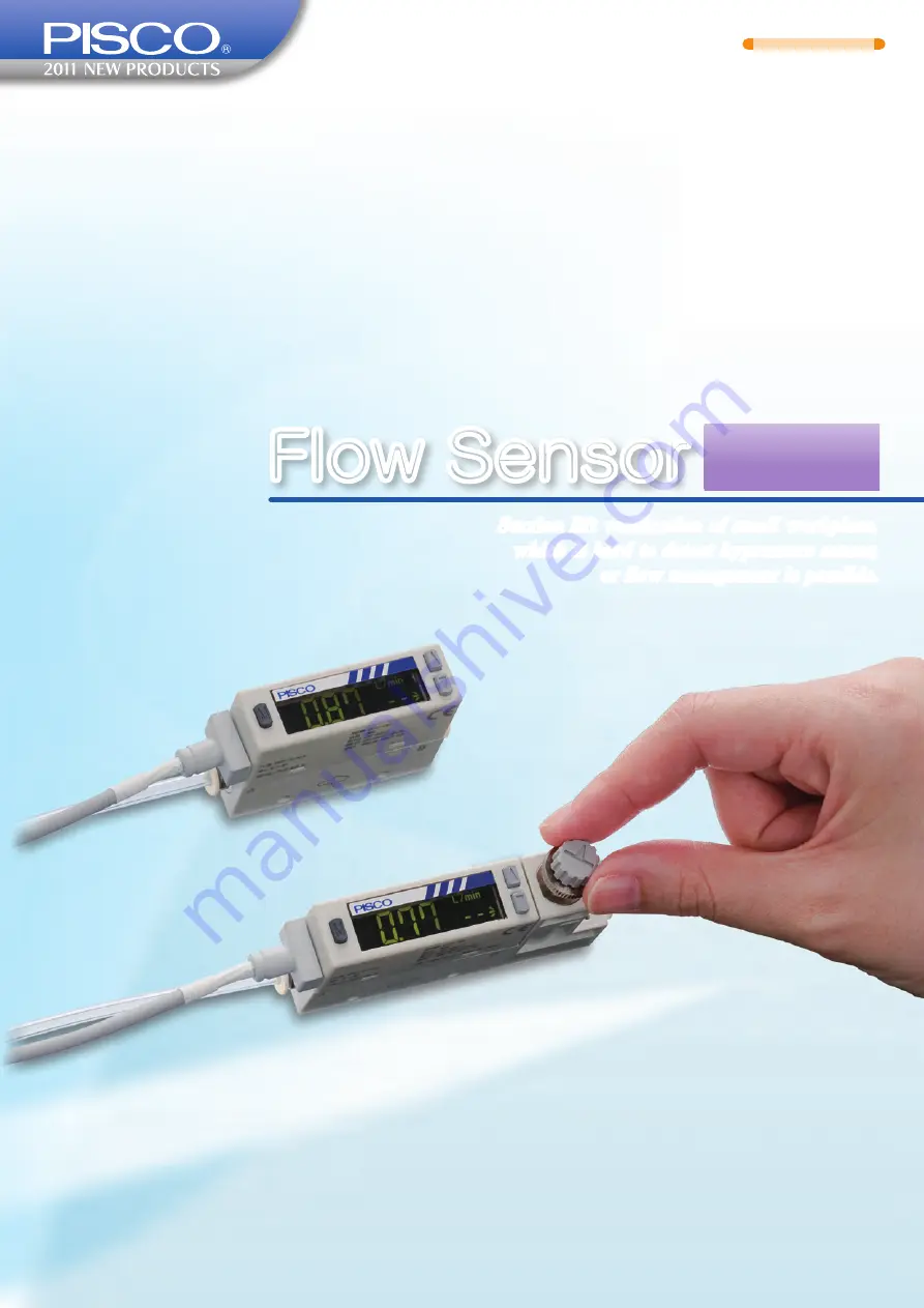
Flow Sensor
Suction lift verification of small workpiece,
which is hard to detect bypressure sensor,
or flow management is possible.
FUS20
Страница 1: ...No IXPN E01 01E Flow Sensor Suction lift verification of small workpiece which is hard to detect bypressure sensor or flow management is possible FUS20 ...
Страница 2: ...ensor are integrated into one unit Fuss free plumbing and minimized installation space are realized Panel mount is possible Bracket for panel mount is available Sensor as well as built in needle valve sensor can be panel mounted Since coherent installation is possible one large panel cut make possible for mounting multiple sensors with minimum space and process Dual display 2 color indication feat...
Страница 3: ...lity of the plumbing installation improves and usable for reverse flow detection Free installing orientation The sensor can be mounted in any orientation top bottom left or right Quick response time Max 50msec High speed response is realized by incorporating a platinum sensor chip processed with silicon micromachining It contributes to shorten takt time No straight piping requires The newly propos...
Страница 4: ...l min 2l min 5l min 10l min 20l min 50l min 100l min 200l min Please refer to the table the combination chart of flow range and tube size Tube dia Code 4 6 8 10 O D ø4mm ø6mm ø8mm ø10mm Please refer to the table the combination chart of flow range and tube size FUS20 N V F 005 Cable Code No code 1 3 Cable No cable 1m 3m Brackets Code No code B P Brackets No bracket With bracket With panel mount op...
Страница 5: ...t in needle valve model No Parts Material LCD cover Acryl resin LCD Switch EPDM Circuit board spacer PC Module holder PA Quick Fitting Joint Sensor gasket FKM Sensor section 1 No Parts Material Fitting fixing pin stainless steel Needle valve body PA Port filter stainless steel O ring FKM Orifice nickel plated brass 3 Fitting fixing pin stainless steel O ring FKM fluororesin coating No Parts Materi...
Страница 6: ...ompressed air JIS B8392 1 1 1 to 1 6 2 and nitrogen gas Max working pressure 0 7MPa Min working pressure 0 09MPa Withstand pressure 1MPa Ambient Temp humidity 0 to 50ºC max 90 RH Working fluid temp 0 to 50ºC no dew condensation Accuracy Assured accuracy range 3 100 F S Linearity display analog output Max 3 F S Air vent for 2ndary side 25ºC Pressure characteristics Max 5 F S 0 09 to 0 7MPa where ai...
Страница 7: ...1 1 1 1 6 2 Please install a filter filtering rate 5µm an air dryer minimum pressure dew point max 10 C and an oil mist filter max oil content 0 1mg m onto the primary side upstream of the sensor since the compressed air from the compressor contains drain water oil oxide and foreign material etc Recommended circuit Unit wieght 空気圧源 流量センサ フィルタ エアドライヤ レギュレータ オイルミストフィルタ 推奨機器 エアフィルタ オイルミス トフィルタ Pressu...
Страница 8: ...15 6 ø8 18 2 ø17 ø10 20 7 Unit mm H1 H4 17 9 5 2 M3 0 5 Depth 5 15 5 80 55 70 min 10 5 max 19 8 27 5 L1 2 3 4 15 L1 27 H2 H3 3 6 Outer dimensions by fitting size ø4 L1 Fitting size 5 6 1 9 17 H1 37 43 H2 8 5 13 H3 24 2 30 2 H4 17 23 ø6 ø8 ø10 ø9 95 ø4 10 9 ø9 95 ø6 11 7 ø15 6 ø8 18 2 ø17 ø10 20 7 Unit mm 8 FUS20 No needle valve FUS20 Built in needle valve Model FUS20 Model FUS20 N Terminal no Cabl...
Страница 9: ...ww pisco co jp 5 25 L Max 30 Halogen free cable Half stripped Heat shrinkable tube Connector cover Material EPDM 2 ø3 5 17 27 5 1 R1 75 8 4 2 3 5 14 5 4 9 5 15 5 2 6 30 55 2 fixing screws M3 0 5 length 6mm are included 9 FUS20 C5 5 core cable FUS20 B1 Bracket Unit mm Model L FUS20 C51 1040 20 FUS20 C53 3040 20 Terminal no Cable color Wiring destination 1 Brown DC12 24V 2 Black CH1 OUT1 3 White CH2...
Страница 10: ...ensions by fitting size ø4 L1 Fitting size 5 6 1 9 17 H1 40 5 46 5 H2 28 5 30 ø6 ø8 ø10 ø9 95 ø4 10 9 ø9 95 ø6 11 7 ø15 6 ø8 18 2 ø17 ø10 20 7 Unit mm 28 28 2 fixing screws M3 0 5 Tightening torque 0 06N m 20 Panel holder cover Panel stopper Panel holder 4 15 H1 H2 1 4 80 18 28 88 78 95 4x max R1 4x max R1 22 5 28 n 1 74 5 0 5 22 5 0 5 74 5 0 5 L1 L1 Panel cut dimensions Single installation Cohere...
Страница 11: ...e Gray Analog output Blue Power source Black CH1 SW output 1 White CH2 External input 1 2 3 4 5 Using CH2 as SW output Using CH2 as external input FUS20 side R R Analog voltage output type R about 1KΩ Analog current output type R about 100Ω Main circuit Main circuit 11 Internal circuit and load connection example NPN output model PNP output model Terminal no Optional cable color Wiring destination...
Страница 12: ...flow direction Current output type one way flow direction Voltage output type bidirectional flow direction Current output type bidirectional flow direction flow rate l min 0 F S flow rate 5 1 3 flow rate l min 0 F S flow rate 20 4 12 F S flow rate F S flow rate 0 5 1 3 flow rate l min flow rate l min 20 4 12 F S flow rate F S flow rate 0 analog output V analog output mA analog output V analog outp...
Страница 13: ... 06 0 08 0 1 0 12 0 14 0 16 0 18 0 2 0 1 0 8 0 6 0 4 0 2 flow rate l min 0 1MPa 0 3MPa 0 5MPa 0 0 05 0 1 0 15 0 2 0 25 0 3 0 35 0 4 0 45 0 5 0 2 1 5 1 0 5 flow rate l min 0 1MPa 0 3MPa 0 5MPa 0 0 2 0 4 0 6 0 8 1 1 2 1 4 1 6 5 4 3 2 1 0 flow rate l min 0 1MPa 0 3MPa 0 5MPa 0 0 5 1 1 5 2 2 5 3 3 5 4 4 5 0 1 8 6 4 2 0 flow rate l min 0 1MPa 0 3MPa 0 5MPa 0 0 5 1 1 5 2 2 5 3 3 5 4 4 5 5 0 20 15 10 5 f...
Страница 14: ...otation 0 1 2 3 4 5 6 7 8 9 10 0 14 12 10 8 2 4 6 0 5MPa 0 1MPa flow rate l min ANR FUS20 050 N FUS20 100 N number of needle rotation flow rate l min ANR FUS20 200 N FUS20 500 6 N number of needle rotation flow rate l min ANR FUS20 500 8 N FUS20 101 N FUS20 201 N number of needle rotation 0 5 10 15 20 25 30 35 0 14 12 10 8 2 4 6 0 5MPa 0 1MPa 0 20 40 60 80 100 120 140 160 180 200 0 14 12 10 8 2 4 ...
Страница 15: ... data using count down numbers etc Main display green red Display set value and flow rate Display color can be changed Display upper 3 digits during accumulated flow rate display Sub display green red Display flow direction and operating status Display color can be changed Display lower 4 digits during accumulated flow display Flow rate unit display green Display flow rate unit Output OUT1 display...
Страница 16: ...n the specified accumulated value is exceeded and an accumulated pulse function that outputs a pulse after a set count value It will be reset if power is turned off and can be reset with button operation or external input Real time flow display Peak hold function Maximum and minimum flow rates within a set interval are displayed Peak hold OFF Key lock function Key operations are disabled to preven...
Страница 17: ...se are prevented Response time Max 50ms Display speed setting The digital display s update cycle is set in 3 stages from 250 ms to 1 sec Display blinking is minimized by making the display update cycle longer Display speed 250ms Sub display setting Set the sub display indication selecting from flow direction flow unit or fluid medium display Ai for air or N2 type Flow direction Display color setti...
Страница 18: ...ower flow rate side ON Hysteresis is set arbitrarily and when the flow reaches and exceeds the designated flow level switch output goes OFF Flow rate ON OFF ON set value OFF setting Hysteresis operation 2 Larger flow rate side ON Hysteresis is set arbitrarily and when the flow reaches and exceeds the designated level switch output goes ON Flow rate ON OFF ON set value OFF setting Accumulated outpu...
Страница 19: ...switch turns ON when on or higher than the read value Threshold input value Flow rate ON OFF Input value Sub display Main display OFF above input value The switch goes OFF when on or higher than the read value Threshold input value Flow rate ON OFF Input value 2 points ON above the mean value of 2 points The switch goes ON when on or higher than the mean value of two read points Threshold input 1 ...
Страница 20: ...y button operations Flow direction LCD display Analog output characteristic Bidirectional The arrow direction changes according to the flow direction Minus indication with reverse flow direction Main display Sub display F S flow rate 0 F S flow rate Reverse direction analog output Forward direction 5 20 3 12 1 4 V mA l min One way forward direction Main display Sub disply l min 0 F S flow rate 5 2...
Страница 21: ... used for the temperature sensor When the heater is turned on and heated the temperature distribution is symmetrical about the center of the heater if there is no flow When flow is received the symmetrical property of temperature distribution is lost and temperature upstream of the heater drops and that downstream rises This difference of temperature becomes the difference of the resistance level ...
Страница 22: ... 02 Subsonic 0 072 0 287 0 645 1 147 1 792 3 512 7 166 16 125 28 666 0 1013 0 0 0913 0 01 Subsonic 0 054 0 215 0 483 0 859 1 343 2 631 5 370 12 083 21 480 0 1113 0 01 0 1013 0 Subsonic 0 057 0 226 0 509 0 905 1 414 2 772 5 657 12 727 22 626 0 1213 0 02 0 1013 0 Subsonic 0 080 0 320 0 720 1 280 2 000 3 920 8 000 17 999 31 998 0 1413 0 04 0 1013 0 Subsonic 0 113 0 453 1 018 1 810 2 828 5 543 11 313 ...
Страница 23: ...time on piping becomes as shown below Based on this to shorten response time the inner volume of piping should be minimized Pressure source 20kPa Nozzle ø0 25 A B 3 way valve Test circuit FUS20 Vacuum source 70kPa 2 Using collet nozzle A collet nozzle is often used when the workpiece to be picked up should not be directly seated against the nozzle The collet nozzle is shaped like a pyramid so when...
Страница 24: ...itial performance and safety of the system is on responsibility of the person who decides specifications Hereafter examine all the specification with updated products catalogues and technical documents in order to avoid malfunctions of equipment and then develop systems 2 Handle pneumatic equipment with enough knowledge and experience 1 Mishandling of compressed air is dangerous Conduct assembly o...
Страница 25: ...rns on you 6 Do not allow tension twist or bending forces to act on the products Undue forces may damage theproducts 7 For applications in which the threaded side or the tube connection side is subject to swinging or rotation use Rotary Joints High Rotary Joints or Multi Circuit Rotary Blocks only Swinging or rotation may damage the joint body 8 Except for Die Temp Control Fitting Tube Fitting Sta...
Страница 26: ...ays looses Most of causes of loosing tube are shear drop of fore end of lock claws and abnormal small tube outer diameter Therefore please insert the tube following the procedure of fitting of tube 1 to 3 even if the lock claws is not observed 7 Cautions on the release of tube 1 Before releasing the tube make certain that the pressure inside the tube is zero 2 Push the release ring fully inside an...
Страница 27: ...tion of a product please tighten it with a proper tool using outer hexagonal part or internal hexagonal part Please pay attention that the tool and lock claws are not come in contact when inserting the tool into hexagonal hole The loss of tube lock function may be caused by deformation of fore end of lock claws and may cause loosing tube 2 In tightening the screw use the tightening torque recommen...
Страница 28: ...les for use and selections of pneumatic cylinder High Pressure Gas Maintenance Law Occupational Safety and Sanitation Laws other safety regulations corporate standards and etc 4 Please do not handle the products plumbing nor remove components before confirming safety 1 Please inspect and service the machines and devices after confirming safety of the entire system related this product 2 Care must ...
Страница 29: ...explosion proof explosion or fire may be caused Warnings Corrosive environment Please do not use the product in an environment containing corrosive gas such as sulfurous acid gas or etc Ambient fluid temperature Please use the product within the ambient fluid temperature ranges 0 to 50 C Even in the specified temperature range please do not use the product where ambient fluid temperatures change s...
Страница 30: ... of suction side to prevent suction of foreign materials When using this product with suction lift verification etc considering atmospheric dew point and ambient temperature of this product please use the product under the conditions that dew condensations will not be formed in the inside of pipe When using this product with suction lift verification etc response time may delay per piping volume b...
Страница 31: ...rque of fixing screw is 0 5N m Tightening torque of fixing screw is 0 5N m Panel mount installation Fixing screw 1 Tightening torque of fixing screw is 0 06N m 2 Please make plumbing before installation 3 If plumbing is made after installation the part may be broken by excessive force 4 If panel mounting is selected please avoid vibrations are not affecting to the sensor 3 Wiring Danger Power supp...
Страница 32: ...ower 100VAC is applied it may cause a damage or burn This product and wiring must be installed as far away as possible from noise source such as strong electric line etc Please take other countermeasures for a surge on the power supply line Please do not short circuit a load or causing damage or burn Output impedance of analog voltage output type is approximately 1 kΩ If the impedance of connectin...
Страница 33: ...be done at least once a year then please make sure that the product be operated properly Disassembly and modification must not be done or causing a failure The material of case is resin Solvent alcohol cleaner etc must not be used to remove contamination etc or causing a resin to be corroded Please wipe with diluted neutral detergent by tightly squeezed waste cloth etc Please be careful of reverse...
Страница 34: ...on Surge absorbing element Integrated Circuit shutdown by disconnection or emergency stop Surge absorbing element Later installation Flow sensor Surge current PLC output PLC ON Main Circuit Relay Solenoid Valve Please be careful of leading of surge current If the flow sensor shares the power source with inductive load forming surge of a solenoid valve or a relay etc when a circuit is disconnected ...
Страница 35: ...roduct cannot be used as shut off valve requiring no leakage A certain degree of leakage is allowed as specifications Please select and use a clean filter scch as hollow fiber membrane filter MFU or etc if dusts and particles which are generated in a flow path of needle valve causes a problem 2 Installation adjustment Caution Please do not turn the needle with excessive force at the time of full o...
Страница 36: ...NAMIMINOWA KAMIINA NAGANO PREF 399 4588 JAPAN Tel 81 0 265 76 7751 Fax 81 0 265 76 3305 Website http www pisco co jp english pisco htm E mail intl pisco co jp The specifications are subject to change without advance notice 2012 02 PDF ...