169
Integrator Mode
7
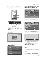
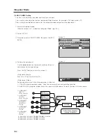
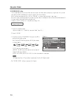
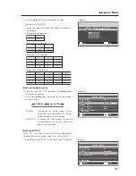
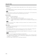
Setting the ABL LINK
This option synchronizes the screen brightness on the multiple displays that form a Video Wall.
Apply the AUTO ID function the select a screen divider option (other than OFF).
~
Place the cursor on ‘ABL LINK’ then press the [
2
/
3
]
buttons to change the settings.
Each time a [
2
/
3
] button is pressed, the setting changes
as shown below.
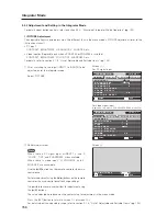
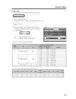
[Setting the ABL LINK]
ON ........... Brightness of each screen on the video wall is
the same (available for 4-panel and 9-panel
video walls only).
OFF ......... Brightness of the screens depends on the
setting of each display.
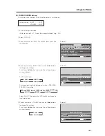
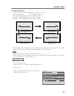
[Connecting four displays]
When this option is ‘ON’, connect the four displays
according to the POSITION sequence numbers in the
figure on the right with the combination cable (Mini-DIN,
6 pin). If the screen division or POSITION has changed,
the ABL link automatically turns off.
Note
Connect in the same way for a 9-panel video wall.
7
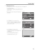
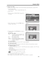
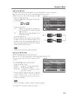
Setting the REPEAT TIMER
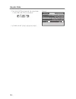
REPEAT TIMER duplicates the timed activities twice.
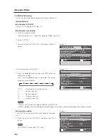
Apply the ‘AUTO ID’ function then select a screen divider option (other than OFF).
!
Set the cursor on ‘REPEAT TIMER’ then press the [SET]
button.
@
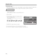
Use the
5
/
∞
/
2
/
3
buttons to change settings.
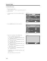
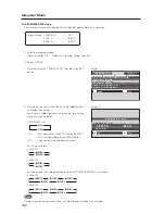
[Setting the REPEAT TIMER]
DIVIDER ......... Setting the 1, 4, and 9 screen displays
SOURCE ........ Setting the input displayed
WORK TIME .. It can be set in 1 minute units up to 4
hours and 15 minutes
When the REPEAT TIMER has run twice, it alternately
switches between REPEAT TIMER1 and REPEAT
TIMER2. A video wall, only the panel in position ID1
controls all the settings.
Note
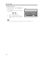
REPEAT TIMER goes in to effect when the OSD display disappears.
The ‘VIDEO WALL’ settings are common for all inputs.
Screen
~
3
ON
OFF
2
3
2
V I D E O WA L L
N O R M A L
O F F
O F F
:
:
:
O F F
:
SET
EXIT
MENU
D I V I D E R
T Y P E
A U T O I D
P . O N D E L AY
A B L L I N K
R E P E A T T I M E R
R E T U R N
P O S I T I ON
Display 1
Display 2
Display 3
Display 4
No.1 No.2
No.3
No.4
No.1 No.2
No.3
No.4
No.1 No.2
No.3
No.4
No.1 No.2
No.3
No.4
COMBINATION
IN
COMBINATION
OUT
COMBINATION
OUT
COMBINATION
IN
COMBINATION
IN
COMBINATION
OUT
COMBINATION
OUT
COMBINATION
IN
Screen
!
0 0 H 0 1 M
I N P U T 1
4
0 0 H 0 1 M
I N P U T 2
4
1
2
:
:
:
:
:
:
SET
SET
EXIT
MENU
D I V I D E R
WOR K T I M E
R E P E A T T I M E R
S O U RC E
D I V I D E R
WOR K T I M E
S O U RC E
Содержание PDA-5003
Страница 81: ...81 Ceiling Mount Unit PDK 5012 ...

