PRO-1010HD
146
1
2
3
4
1
2
3
4
C
D
F
A
B
E
10
2
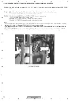
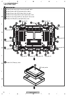
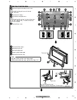
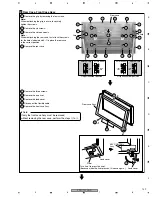
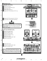
Remove the two hexagon head screws.
1
Remove the four screws.
3
Remove the one screw.
4
Remove the one pin grommet.
5
Remove the AV I/O Assy with the AV I/O I/F Assy.
6
Remove the AV I/O Assy from the AV I/O I/F Assy.
7
Connect the AV I/O Assy to slot of the RGB Assy.
2
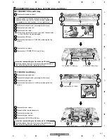
Remove the COMM SLOT Assy.
3
Remove the two Torque screws.
4
Remove the VIDEO SLOT 1 Assy.
5
Remove the nine screws.
6
Disconnect the some connectors at need.
7
Remove the terminal panel.
8
Remove the two screws.
9
Disconnect the some connectors at need.
Remove the multi base section.
1
Remove the two Torque screws.
Multi Base Section
3
AV I/O Assy
AV I/O Assy
AUDIO AMP Assy
VIDEO SLOT I/O Assy
COMM SLOT
Assy
RGB Assy
AV I/O I/F Assy
5
5
8
8
5
5
5
5
5
5
5
7
10
5
Terminal panel
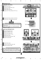
Diagnosis
Diagnosis of AV I/O Assy
Removing Multi Base Section
2
1
3
4
×
2
1
1
1
3
3
1
2
4
1
7
VIDEO SLOT 1
Assy
AV I/O I/F Assy
RGB Assy
AV I/O Assy
Note:
Some tiny metal shavings may be released from the paring
screw section when the VIDEO SLOT I/F Assy is detached from
the sheet metal and is reattached to it. Be sure to clear away any
shavings or other foreign matter before reattaching it to the RGB
Assy.
Note:
The cooling fan may rotate during diagnosis, in the following cases:
• When the rotation speed of the fan has been set to maximum for
Integrator mode
• When the ambient temperature surrounding the temperature
sensor is 35˚C or higher

