160
PDP-5020FD
1
2
3
4
A
B
C
D
E
F
1
2
3
4
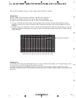
The assembly must be replaced as a unit, and no
part replacement is allowed.
POWER SUPPLY Unit
MAIN Assy
IO AUDIO Assy
No adjustment is required after replacement of parts
other than those shown in “8.5 ADJUSTMENT
WHEN THE DRIVE ASSYS ARE REPLACED.
No adjustment is required after replacement of parts
other than those shown in “8.7 ADJUSTMENT WHEN
THE MAIN OR IO_AUDIO ASSY IS REPLACED.
No adjustment is required after replacement of parts
other than those shown in “8.7 ADJUSTMENT WHEN
THE MAIN OR IO_AUDIO ASSY IS REPLACED.
No adjustment is required after replacement of parts
other than those shown in “8.5 ADJUSTMENT
WHEN THE DRIVE ASSYS ARE REPLACED.
No adjustment required
DIGITAL Assy
No adjustment required
X DRIVE Assy
Y DRIVE Assy
No adjustment required
Other assemblies
ADDRESS Assy
No adjustment required
PANEL SENSOR Assy
Содержание ARP3476
Страница 10: ...10 PDP 5020FD 1 2 3 4 A B C D E F 1 2 3 4 2 2 SPECIFICATIONS ...
Страница 11: ...11 PDP 5020FD 5 6 7 8 5 6 7 8 A B C D E F ...
Страница 12: ...12 PDP 5020FD 1 2 3 4 A B C D E F 1 2 3 4 2 3 PANEL FACILITIES Front Section ...
Страница 13: ...13 PDP 5020FD 5 6 7 8 5 6 7 8 A B C D E F Rear Section ...
Страница 14: ...14 PDP 5020FD 1 2 3 4 A B C D E F 1 2 3 4 Remote Control Unit ...
Страница 15: ...15 PDP 5020FD 5 6 7 8 5 6 7 8 A B C D E F ...
Страница 21: ...21 PDP 5020FD 5 6 7 8 5 6 7 8 A B C D E F ...
Страница 22: ...22 PDP 5020FD 1 2 3 4 A B C D E F 1 2 3 4 4 BLOCK DIAGRAM 4 1 OVERALL WIRING DIAGRAM 1 2 ...
Страница 25: ...25 PDP 5020FD 5 6 7 8 5 6 7 8 A B C D E F OVERALL DIAGRAM PDP 5020FD ...
Страница 31: ...31 PDP 5020FD 5 6 7 8 5 6 7 8 A B C D E F ...
Страница 71: ...71 PDP 5020FD 5 6 7 8 5 6 7 8 A B C D E F ...
Страница 192: ...192 PDP 5020FD 1 2 3 4 A B C D E F 1 2 3 4 9 6 PANEL CHASSIS SECTION ...


