129
PDP-5020FD
5
6
7
8
5
6
7
8
A
B
C
D
E
F
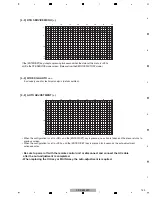
Contents of the Display item
Contents of the Display item
• PM-B1 to B5: The accumulated pulse-meter counts for the 5 blocks on the screen
are indicated. (the lowest-order digit represents millions of pulses.)
• HR-MTR: The hour-meter value (accumulated power-on hours) is indicated.
• P-COUNT: The accumulated power-on count is indicated.
• TEMP1: The current panel temperature and the historical maximum temperature
recorded in memory are indicated. The range of temperature indication is from
-50.0 to +99.9. (The temperature unit is "
°
C (Centigrade) ".)
• CLS-RGB: Data obtained from the color sensor are displayed in the order R, G,
and B, with the status indication at the end.
• Data on operations, such as the accumulated pulse-meter counts, hour-meter count, power-on count, and temperature
detected by the sensor, are displayed. No other layers are nested below this layer, and there are no adjustment items.
[2-2] PANEL WORKS
<DOWN> : Shifting to POWER DOWN
<UP>
: Shifting to PANEL INFORMATION
<L/R>
: Updating displayed information
g
Key operation
Temperature unit is "
°
C (Centigrade) ".
Note:
Turning ON the functions of the color sensor
can be performed in the ETC(+) layer.
A
.
P
N E L
A
P
N E L
O
W
R K S
M
P
– B 1
0 0 0
0
0
M
P
– B 2
0 0 0
0
0
7
5
1
6
7
M
M
0
0 0 0
0
0
0 0 0
0
0
8
2
5
6
8
M
M
6
0 0 0
0
0
7
3
M
3
0 0 0
2
0
5
0 M
2
H
M
P
– B 3
M
P
– B 4
M
P
– B 5
–
P
C O U
T
N
0 0 0
0
0
0
5
9
I
T
M
S
E
L
C
S –
– O K
R
B
G
2 0 0
/
0
0
2 5
3
1
/
2
3
2
E
T
M P 1
+ 2
4
.
7
+ 7
8
.
0
/
R
H
– M T R
F A C T
1
5
10
15
16
1
5
10
15
20
25
30
32
1
2
3
4
5
6
7
8
9
A
B
C
D
E
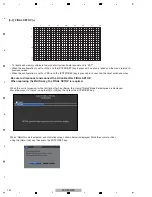
[2-1] PANEL INFORMATION
• Data, such as the version of the microcomputer of the panel, product serial number, and statuses of digital EEPROM for
storing the adjustment values and for backup EEPROM, are displayed. No other layers are nested below this layer, and
there are no adjustment items.
MODULE : The version of data written in the Module microcomputer is indicated.
-PRG
: The program version of the Module microcomputer is indicated.
-DAT
: The data version of the Module microcomputer is indicated.
SEQ PRS : The version of data written in the Sequence LSI is indicated.
-PRG
: The program version of the Sequence LSI is indicated.
-PIC
: The Picture-data version of the Sequence LSI is indicated.
-SEQ
: The sequence-data version of the Sequence LSI is indicated.
SERIAL
: The serial number of the module is indicated.
DIG.EEP : The adjusted status of the EEPROM that is mounted on the DIGITAL Assy is indicated.
BACKUP : The adjusted status of the EEPROM for backup that is mounted on the SENSOR Assy is indicated.
<DOWN> : Shifting to PANEL WORKS
<UP>
: Shifting to COMBI MASK SETUP
(+)
<L/R>
: Updating displayed information
g
Key operation
Details of indications in each layer
A
.
P
N E L
A
P
N
N
E
I
L
F O R
N
T
A
M
O
I
D
O
M
U L E
F A C T
I
–
N 1
3
2
0 6 0
– 0 1 A
– 0 1 A
– 0 1 A
– P R G
– D A T
1 A
0
G
I
D
. E E P
A D
T
J U S
E D
N O
T
D A
A !
C
A
B
K U P
Q
E
S
P R S
– 0 1 Y
– 0 1 Y
– 0 1 Y
– P R Q
– P I C
R
E
S
I A L
_ _ _ _ _ _ _ _ _ _ _ _ _ _ _
– S E Q
5 2 0 Y
2 A
0
– R G B
H
J
–
B
I
–
N 1
3
2
0 6 0
– R G B
H
J
–
B
1
5
10
15
16
1
5
10
15
20
25
30
32
1
2
3
4
5
6
7
8
9
A
B
C
D
E
CLS Status
OSD
Indication
Function OFF
Color sensor module
non connection
Data abnormality
Data normal
-OFF
-NC
-INV
-OK
AREA
AREA
Содержание ARP3476
Страница 10: ...10 PDP 5020FD 1 2 3 4 A B C D E F 1 2 3 4 2 2 SPECIFICATIONS ...
Страница 11: ...11 PDP 5020FD 5 6 7 8 5 6 7 8 A B C D E F ...
Страница 12: ...12 PDP 5020FD 1 2 3 4 A B C D E F 1 2 3 4 2 3 PANEL FACILITIES Front Section ...
Страница 13: ...13 PDP 5020FD 5 6 7 8 5 6 7 8 A B C D E F Rear Section ...
Страница 14: ...14 PDP 5020FD 1 2 3 4 A B C D E F 1 2 3 4 Remote Control Unit ...
Страница 15: ...15 PDP 5020FD 5 6 7 8 5 6 7 8 A B C D E F ...
Страница 21: ...21 PDP 5020FD 5 6 7 8 5 6 7 8 A B C D E F ...
Страница 22: ...22 PDP 5020FD 1 2 3 4 A B C D E F 1 2 3 4 4 BLOCK DIAGRAM 4 1 OVERALL WIRING DIAGRAM 1 2 ...
Страница 25: ...25 PDP 5020FD 5 6 7 8 5 6 7 8 A B C D E F OVERALL DIAGRAM PDP 5020FD ...
Страница 31: ...31 PDP 5020FD 5 6 7 8 5 6 7 8 A B C D E F ...
Страница 71: ...71 PDP 5020FD 5 6 7 8 5 6 7 8 A B C D E F ...
Страница 192: ...192 PDP 5020FD 1 2 3 4 A B C D E F 1 2 3 4 9 6 PANEL CHASSIS SECTION ...


